Wind Power Generation Apparatus, Wind Power Generation System and Power System Control Apparatus

a power generation system and wind power technology, applied in the direction of electric generator control, dynamo-electric converter control, instruments, etc., can solve the problems of deficiency or overflow of reactive power in the entire system, which is not considered in the controlling process, and achieves the effect of suppressing the voltage fluctuation of a coupling point and high output fluctuation

Active Publication Date: 2008-05-08
HITACHI IND PROD LTD
View PDF65 Cites 65 Cited by
  • Summary
  • Abstract
  • Description
  • Claims
  • Application Information

AI Technical Summary

Benefits of technology

[0015]According to the present invention, a wind power generation apparatus can supply necessary reactive power for a power system, and suppress voltage fluctuation of a coupling point of the wind power generation apparatus having high output fluctuation, thereby appropriately adjusting the voltage of the power system although the capability of adjustment equipment for a voltage etc. is exceeded.

Problems solved by technology

Therefore, the deficiency or overflow of the reactive power in the entire system is not considered in the controlling process.
Furthermore, in the apparatus described in U.S. Patent Application Publication No. 20050046196, a reactive power command value is supplied from a farm controller, and the deficiency or overflow of the reactive power on the power system side is not considered in the process of controlling the reactive power of the wind power generation apparatus.

Method used


Image

  • Wind Power Generation Apparatus, Wind Power Generation System and Power System Control Apparatus
  • Wind Power Generation Apparatus, Wind Power Generation System and Power System Control Apparatus
  • Wind Power Generation Apparatus, Wind Power Generation System and Power System Control Apparatus

Examples


embodiment 1

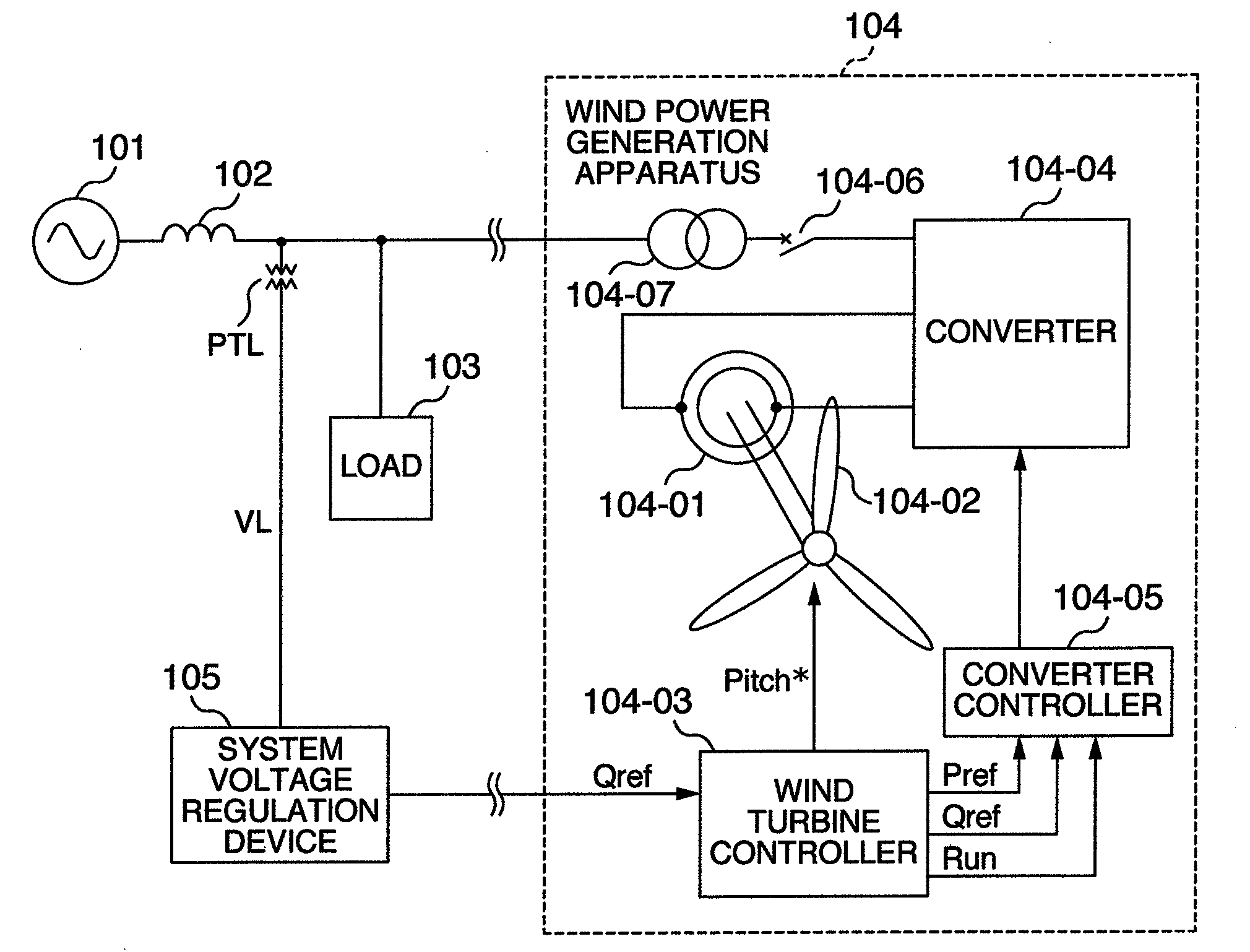
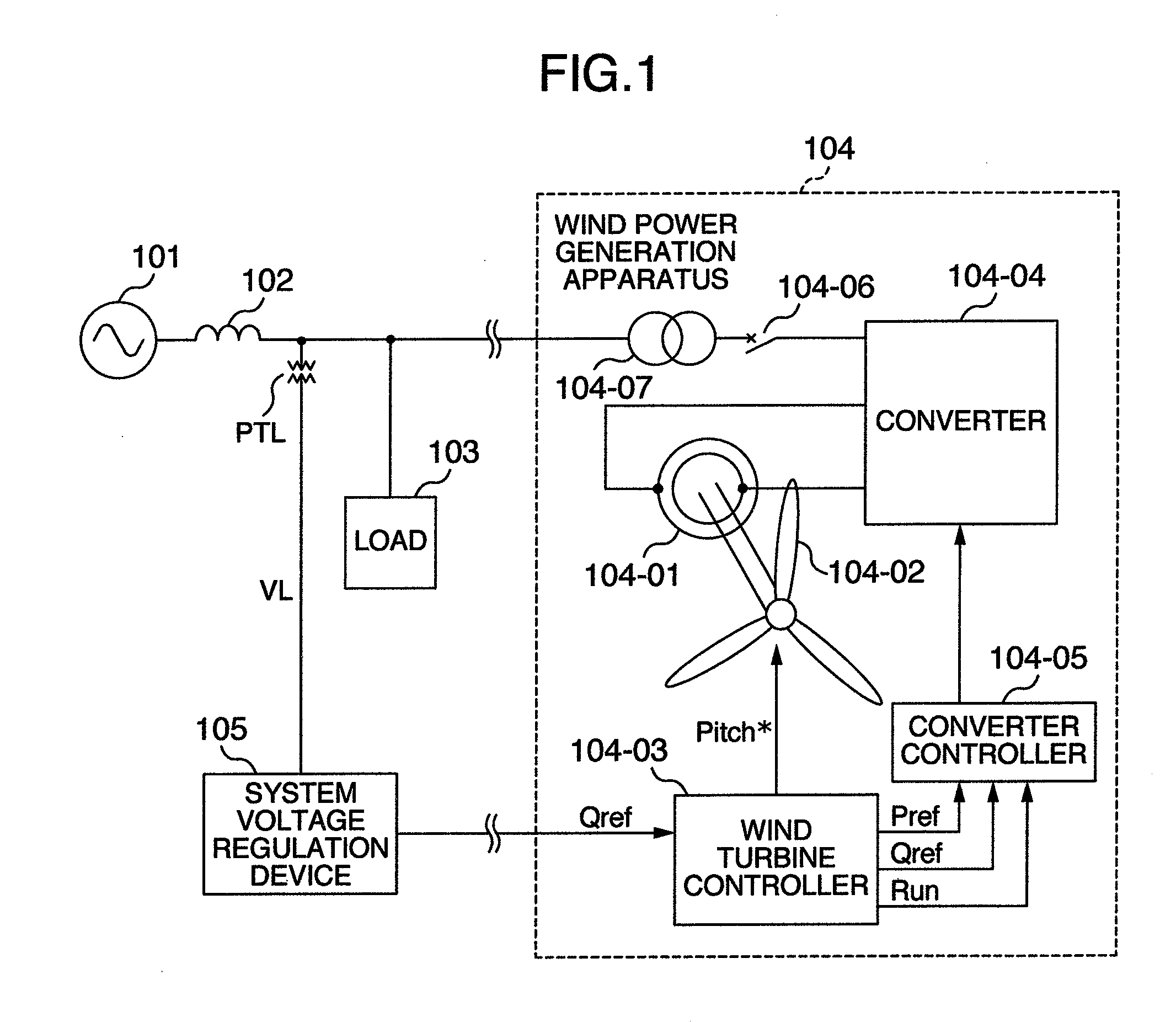
[0027]FIG. 1 is a single line diagram showing the configuration of the apparatus and the power system according to the first embodiment of the wind power generation apparatus of the present invention.

[0028]First described below is the configuration of the power system. A power generation equipment 101 of the power system has a large capacity, and can be regarded simply as a power supply. Since the electric power from the power generation equipment 101 of the power system is transmitted via power lines, impedance 102 of the power lines is considered. A transformer of a substation etc. is used to convert the voltage of the power lines into a lower voltage, and then a load 103 such as user home, buildings, factories are connected. As with the load 103, a wind power generation apparatus 104 is also connected to the power lines.

[0029]A system voltage regulation device 105 is used in a substation. The device regulates the voltage of a load within a predetermined range by regulating the ra...

embodiment 2

[0087]The embodiment 1 describes a wind power generation apparatus in which a wound-rotor induction generator is connected to a system through a converter. However, the present invention can also be applied to a wind power generation apparatus using an inductive generator and a synchronous generator as shown in FIG. 6. The embodiment 2 describes a mode for embodying the present invention using a synchronous generator.

[0088]In a wind power generation apparatus 604 as shown in FIG. 7, for example, a permanent magnetic generator is used, and a converter performs an AC-DC-AC transform on the power produced from the generator and outputs the power to a power system.

[0089]The function of a converter control device 604-05 of the wind power generation apparatus 604 is described below with reference to FIGS. 8 and 9. The components having identical control functions are assigned the identical reference numerals.

[0090]The difference in control of the converter control device 604-05 from the c...


PUM


Abstract

An interface device transmits a reactive power command depending on a power system from a voltage regulation device of the power system to a wind power generation apparatus electrically connected to the power system, and the wind power generation apparatus receives the reactive power command. Then, the wind power generation apparatus outputs reactive power according to a value obtained by adding, to a reactive power command, another reactive power command for suppression of voltage fluctuation caused by output power of the wind power generation apparatus.

Description

CROSS-REFERENCE TO RELATED APPLICATION[0001]The present application relates to subject matters described in a co-pending patent application Ser. No. to be filed on Jun. 28, 2007 entitled “VARIABLE SPEED WIND POWER GENERATION SYSTEM” by Masaya Ichinose, et al. and assigned to the assignees of the present application.BACKGROUND OF THE INVENTION[0002]The present invention relates to a wind power generation apparatus, a wind power generation system and a power system control apparatus for supplying to a power system necessary reactive power for the power system.[0003]Normally, a wind power generation apparatus converts wind energy into rotational energy and generates rotational torque at a rotor of a generator. The apparatus produces electric power from induced torque, and outputs it to a power system, thereby converting the wind energy into active power and supplying the active power to user home and factories connected to the power system.[0004]In addition to the active power consumed...

Claims


Application Information

Patent Timeline
Patent Type & Authority Applications(United States)
IPC IPC(8): H02P9/04F03D9/00G05F1/70H02J11/00
CPCF03D7/0284F03D7/042F03D9/003H02J3/16H02P9/007H02P2101/15H02P23/0081Y02E10/723Y02E10/763Y02E40/34H02J3/386H02P9/305H02P23/26F03D9/255H02J2300/28H02J3/381Y02E10/72Y02E10/76Y02E40/30H02J3/50
Inventor ICHINOSE, MASAYAOOHARA, SHINYAFUTAMI, MOTOO
Owner HITACHI IND PROD LTD
Why Eureka
Try Eureka