Plasma display panel and plasma display device including the plasma display panel

Inactive Publication Date: 2008-05-08
SAMSUNG SDI CO LTD
View PDF11 Cites 5 Cited by
  • Summary
  • Abstract
  • Description
  • Claims
  • Application Information

AI Technical Summary

Benefits of technology

[0009]In exemplary embodiments according to the present invention, a plasma display panel that improves a black area ratio and a bright room contrast by coloring different layers in the panel without having to provide additional elements, is provided.
[0021]According to a plasma display panel of an exemplary embodiment of the present invention, a phosphor layer is colored with a first chromatic color, and a front dielectric layer is colored with a second chromatic color, thereby improving a black area ratio and a bright room contrast of the panel.
[0022]According to another exemplary embodiment, the front dielectric layer is colored with the second chromatic color, the phosphor layer is colored with the first chromatic color, and barrier ribs are colored with a third chromatic color. Thus, the black area ratio and the bright room contrast of the panel are further improved.
[0023]According to another exemplary embodiment, the phosphor layer is colored with the first chromatic color, and the rear dielectric layer is colored with a fourth chromatic color, thereby improving the black area ratio and the bright room contrast of the panel.
[0024]According to another exemplary embodiment, the phosphor layer is colored with the first chromatic color, the rear dielectric layer is colored with the fourth chromatic color, and the barrier rib is colored with the third chromatic color. Thus, the black area ratio and the bright room contrast of the panel are further improved.

Problems solved by technology

As a result, image display capability deteriorates.

Method used


Image

  • Plasma display panel and plasma display device including the plasma display panel
  • Plasma display panel and plasma display device including the plasma display panel
  • Plasma display panel and plasma display device including the plasma display panel

Examples


first embodiment

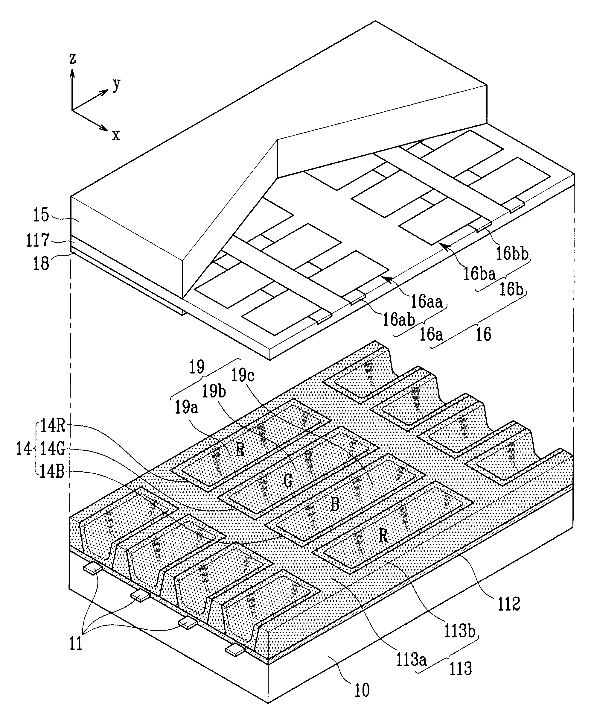
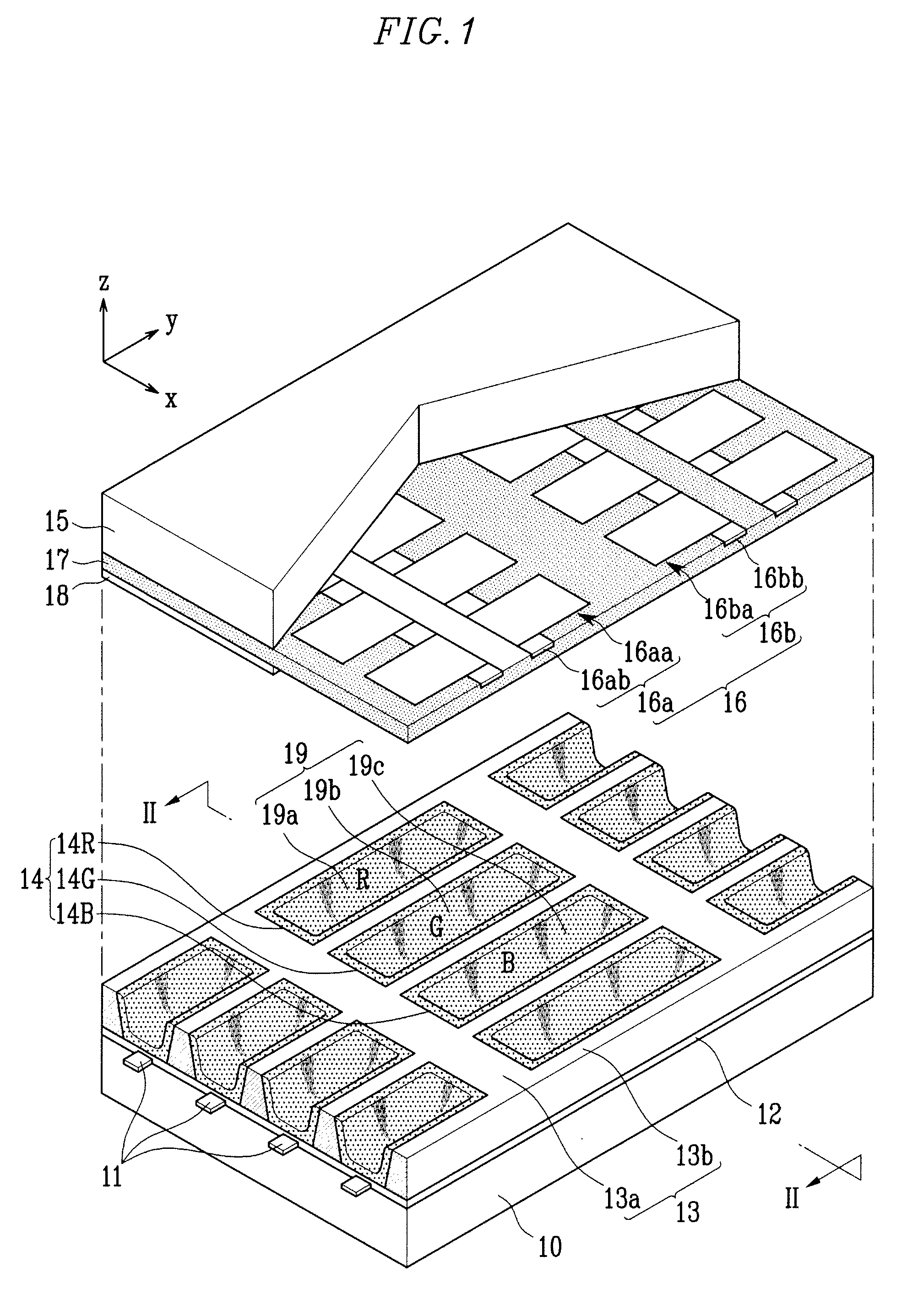
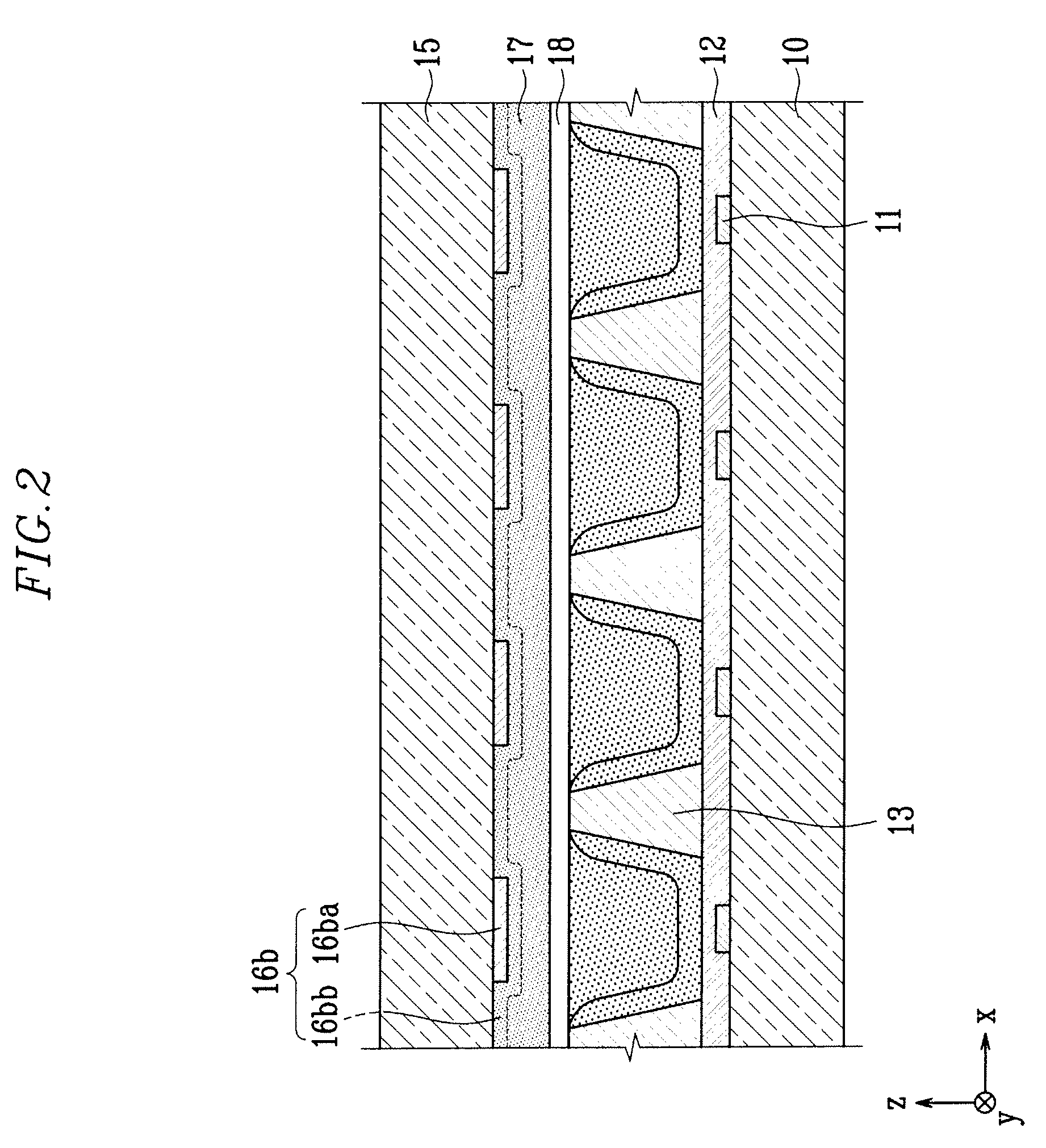
[0041]FIG. 1 is a partial exploded perspective view of a plasma display panel according to the present invention. FIG. 2 is a cross-sectional view of the plasma display panel taken along the line II-II of FIG. 1.

[0042]Referring to FIGS. 1 and 2, the plasma display panel according to the first embodiment of the present invention includes a rear substrate 10, a front substrate 15, barrier ribs 13 that are formed between the two substrates 10 and 15 to define discharge cells 19, address electrodes 11 formed corresponding to the discharge cells 19, and display electrodes 16.

[0043]The rear substrate 10 and the front substrate 15 face each other in parallel with a specific distance therebetween. The address electrodes 11 extend in a first direction (i.e., y-axis direction in FIGS. 1 and 2) on the upper surface (as illustrated in FIGS. 1 and 2) of the rear substrate 10. The address electrodes 11 are adjacent with one another in parallel with a specific distance therebetween.

[0044]A rear di...

second embodiment

[0073]the present invention will now be described with reference to FIGS. 5 and 6. The same elements will be referenced by the same reference numbers. The same description will not be repeated.

[0074]Referring to FIG. 5, a front dielectric layer 17 is colored with a second color. A phosphor layer 14 is colored with a first color. Barrier ribs 113 (113a and 113b) are colored with a third color (e.g., third chromatic color). The barrier ribs 113 (113a and 113b) are substantially the same as the barrier ribs 13 (13a and 13b) of FIG. 1, except that the barrier ribs 113 are colored with the third color. In one exemplary embodiment, the third color is substantially the same as the first color. In other embodiments, the first and third colors may be same or different.

[0075]Referring to FIG. 6, the plasma display panel has an image display area 40 on which an image is displayed. Only a part of the image display area 40 is shown in FIG. 6.

[0076]The image display area 40 includes a first area ...

third embodiment

[0079]the present invention will now be described with reference to FIGS. 7 and 8. The same elements will be referenced by the same reference numbers. The same description will not be repeated.

[0080]According to this embodiment of the present invention, a rear dielectric layer 112 is colored with a fourth color (e.g., fourth chromatic color). The rear dielectric layer 112 is substantially the same as the rear dielectric layer 12 of FIG. 1, except that the rear dielectric layer 112 is colored with the fourth color. A phosphor layer 14 is colored with a first color. The first and fourth colors are selected for their subtractive mixture properties. In particular, in this embodiment of the present invention, the fourth color of the rear dielectric layer 112 and the first color of the phosphor layer 14 are complementary colors with respect to each other.

[0081]Referring to FIG. 8, the plasma display panel has an image display area 50 on which an image is displayed. Only a part of the imag...


PUM


Abstract

Provided is a plasma display panel that improves a black area ratio and a bright room contrast. The plasma display panel includes: front and rear substrates facing each other; barrier ribs disposed between the front and rear substrates to define discharge cells; address electrodes which extend in a first direction on the rear substrate and correspond to the discharge cells; a plurality of phosphor layers disposed in the discharge cells, wherein at least one of the phosphor layers is colored with a first chromatic color; display electrodes which extend in a second direction crossing the first direction on the front substrate and correspond to the discharge cells; and a front dielectric layer which is disposed on the front substrate to cover the display electrodes. The front dielectric layer is colored with a second chromatic color. The barrier ribs may be colored with a third chromatic color.

Description

CROSS-REFERENCE TO RELATED PATENT APPLICATION[0001]This application claims priority to and the benefit of Korean Patent Application No. 10-2006-0107738, filed on Nov. 2, 2006, in the Korean Intellectual Property Office, the entire content of which is incorporated herein by reference.BACKGROUND OF THE INVENTION[0002](a) Field of the Invention[0003]The present invention relates to a plasma display panel, and more particularly, to a plasma display panel having an improved black area ratio and bright room contrast.[0004](b) Description of the Related Art[0005]In general, a plasma display panel uses a vacuum ultraviolet (VUV) ray which is irradiated from plasma obtained through a gas discharge. The VUV ray excites a phosphor material. The excited phosphor material is stabilized to generate visible light. According to a type of phosphor material, the visible light is viewed as red, green, or blue. These color components are properly combined to form an image.[0006]For example, an AC-type ...

Claims


Application Information

Patent Timeline
IPC IPC(8): H01J1/62
CPCH01J11/12H01J11/36H01J11/38H01J2211/444H01J11/44H01J2211/42H01J11/42H01J11/24
Inventor HONG, CHONG-GI
Owner SAMSUNG SDI CO LTD
Why Eureka
Try Eureka