Controller for vehicle AC generator

a controller and ac generator technology, applied in the direction of electric generator control, generator control by field variation, dynamo-electric converter control, etc., can solve the problem of long and achieve the effect of reducing the time required for aging in an initial tes

Inactive Publication Date: 2008-05-08
MITSUBISHI ELECTRIC CORP
View PDF9 Cites 5 Cited by
  • Summary
  • Abstract
  • Description
  • Claims
  • Application Information

AI Technical Summary

Benefits of technology

[0007]The invention provides an improved controller for a vehicle AC generator including a CMOS logic circuit that allows the time required for aging in an initial test to be reduced.
[0009]The controller for use in a vehicle AC generator according to the invention includes the excitation switch connected to the second external terminal to control field current passed through the field coil, the excitation control circuit connected to the first external terminal to control the on / off state of the excitation switch based on the generator voltage, the specified signal detecting circuit connected to the third external terminal to detect a specified signal, the voltage selector circuit that generates a voltage selector signal in response to the detection output of the specified signal detecting circuit, and the power supply circuit connected to the first external terminal to output either one of the first power supply voltage or the second power supply voltage higher than the first power supply voltage as the internal power supply voltage, based on the voltage selector signal, the controller is constructed by using a CMOS logic circuit at least as a part thereof, and the power supply circuit outputs the first supply voltage in a first state in which the specified signal is not input to the third external terminal and the second supply voltage in a second state in which the specified signal is input to the third external terminal and supplies the internal power supply voltage to at least the CMOS logic circuit. In this way, the specified signal is input to the third external terminal when aging is carried out in an initial test, so that the aging time of the CMOS logic circuit can be reduced.

Problems solved by technology

The initial test is carried out to test the function of the semiconductor integrated circuit, while a short term function test does not clarify functional failures in the CMOS logic circuit and therefore aging for a long period is necessary.

Method used


Image

  • Controller for vehicle AC generator
  • Controller for vehicle AC generator
  • Controller for vehicle AC generator

Examples


first embodiment

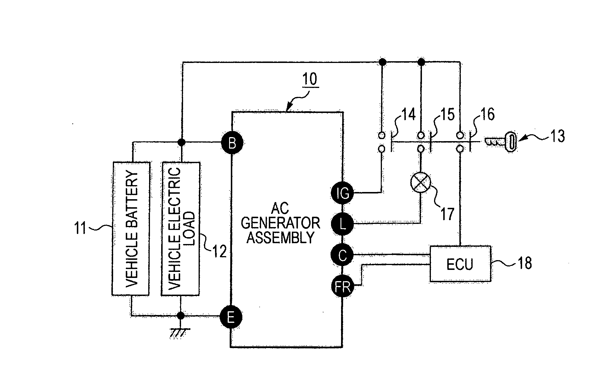
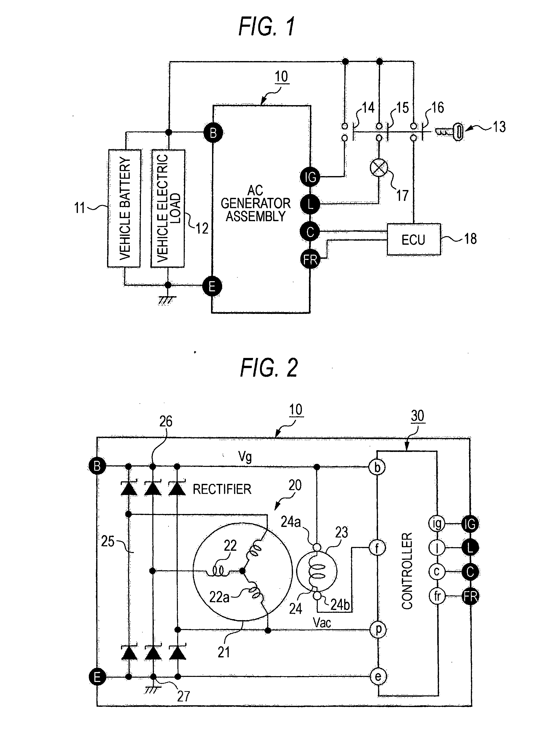
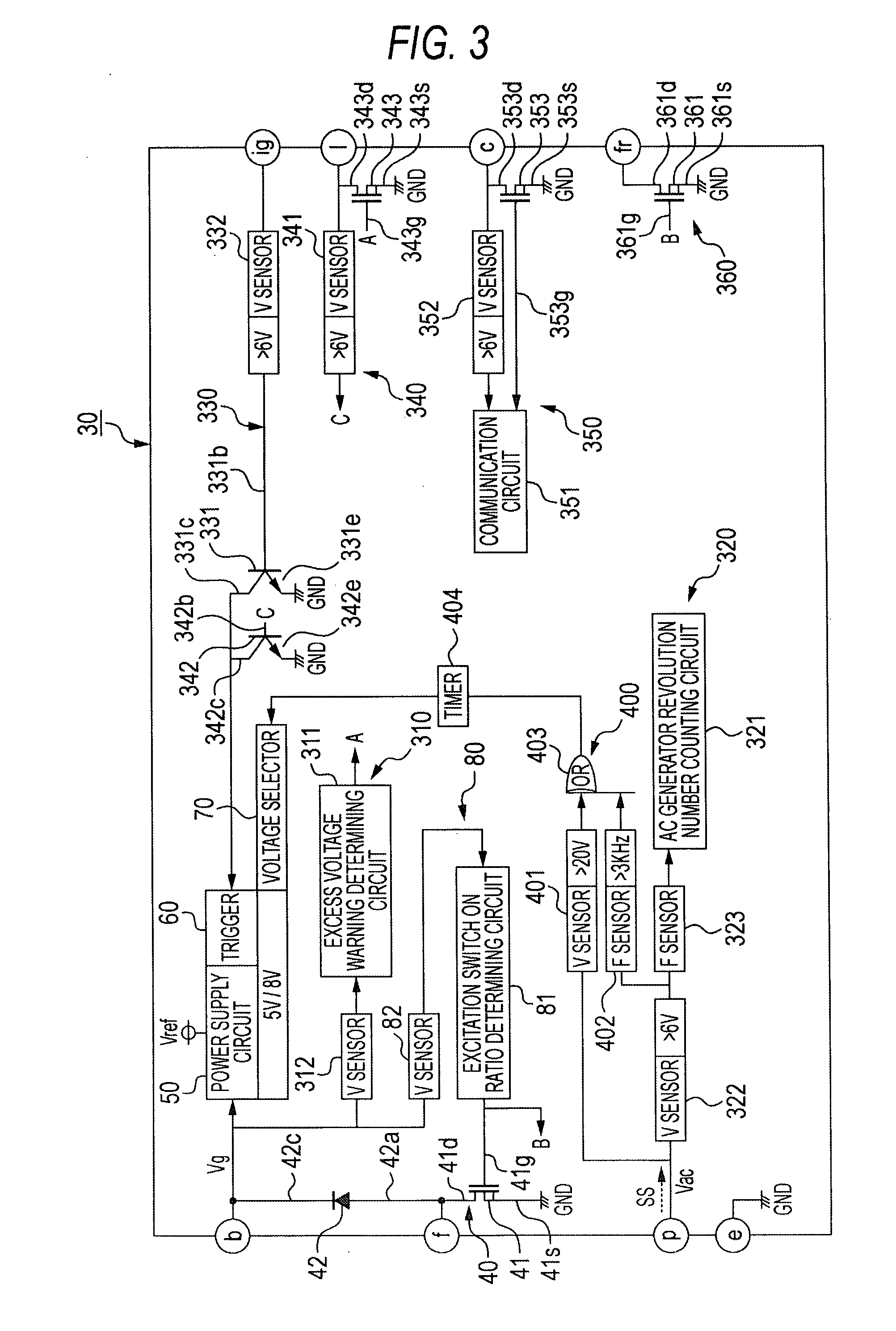
[0021]FIG. 1 is a diagram of a general configuration of a vehicle electric system including a controller for a vehicle AC generator according to the invention, FIG. 2 is an internal circuit diagram of an AC generator assembly including a controller for a vehicle AC generator according to the invention, and FIG. 3 is a block circuit diagram of a controller for a vehicle AC generator according to a first embodiment of the invention.

[0022]The vehicle electric system shown in FIG. 1 includes an AC generator assembly 10, a vehicle battery 11, a vehicle electric load 12, a vehicle ignition switch 13, an abnormality indicator lamp 17, and an engine electronic control unit (ECU) 18. The AC generator assembly 10 has B, E, IG, L, C, and FR terminals. The vehicle battery 11 and the vehicle load 12 are connected between the B and E terminals of the AC generator assembly 10. The vehicle battery 11 is for example a 12-volt battery and has its positive terminal connected to the B terminal of the A...

second embodiment

[0057]FIG. 6 is a block circuit diagram of a controller for a vehicle AC generator according to a second embodiment of the invention. According to the second embodiment, a controller 30A shown in FIG. 6 is used in place of the controller 30 according to the first embodiment. In the controller 30A, the specified signal SS is supplied to the ig terminal of the controller 30A, and the specified signal detecting circuit 400 and the functional circuit 330 are connected together to the ig terminal. The other configuration is the same as that of the controller 30 according to the first embodiment. In the second controller 30A according to the second embodiment, the specified signal detecting circuit 400 the same as that of the first embodiment is used.

[0058]In the controller 30A, the voltage sensor 401 of the specified signal detecting circuit 400 is directly connected to the ig terminal of the controller 30A, and the frequency sensor 402 of the specified signal detecting circuit 400 is co...

third embodiment

[0060]FIG. 7 is a block circuit diagram of a controller for a vehicle AC generator according to a third embodiment of the invention. According to the third embodiment, a controller 30B shown in FIG. 7 is used in place of the controller 30 according to the first embodiment. In the controller 30B, the specified signal SS is supplied to the l terminal of the controller 30B, and the specified signal detecting circuit 400 and the functional circuit 340 are connected together to the l terminal. The other configuration is the same as that of the controller 30 according to the first embodiment. In the controller 30B according to the third embodiment, the specified signal detecting circuit 400 the same as that of the first embodiment is used.

[0061]In the controller 30B, the voltage sensor 401 of the specified signal detecting circuit 400 is directly connected to the l terminal of the controller 30B and the frequency sensor 402 of the specified signal detecting circuit 400 is connected to the...


PUM


Abstract

A controller for a vehicle AC generator that allows the aging test time of a CMOS logic circuit to be reduced is provided. The controller includes a specified signal detecting circuit connected to a third external terminal to detect a specified signal, a voltage selector circuit that generates a voltage selector signal in response to the detection output of the specified signal detecting circuit, and a power supply circuit connected to the first external terminal to output, as internal power supply voltage, first power supply voltage in a first state in which the specified signal is not input to the third external terminal and second power supply voltage higher than the first power supply voltage in a second state in which the specified signal is input to the third external terminal.

Description

BACKGROUND OF THE INVENTION[0001]1. Field of the Invention[0002]The invention relates to a controller for a vehicle AC generator for use in a vehicle.[0003]2. Description of the Related Art[0004]A controller for a vehicle AC generator of this kind controls the on / off state of field current passed through a field coil in response to the voltage of the vehicle AC generator and controls the generator voltage of the vehicle AC generator. A voltage controller disclosed by JP2002-95297A includes switch means that controls field current, a control circuit that controls the on / off state of the switch means in response to the voltage of the generator, a power supply circuit for the control circuit, and a voltage controller having a power supply driving circuit that drives the power supply circuit.[0005]A semiconductor integrated circuit is generally used for such a controller for a vehicle AC generator, and for achieving reduced power consumption, a CMOS logic circuit as a CMOS semiconductor...

Claims


Application Information

Patent Timeline
Patent Type & Authority Applications(United States)
IPC IPC(8): H02P9/04
CPCH02P9/30H02P9/305H02P2101/45H02J7/14H02P9/48
Inventor SUMIMOTO, KATSUYUKI
Owner MITSUBISHI ELECTRIC CORP
Why Eureka
Try Eureka