A Position Detecting Device With A Microwave Antenna Arrangement

Inactive Publication Date: 2008-05-08
FESTO AG & CO KG
View PDF7 Cites 15 Cited by
  • Summary
  • Abstract
  • Description
  • Claims
  • Application Information

AI Technical Summary

Benefits of technology

[0007]One object of the present invention is to provide a position detecting device with improved emitting and / or receiving characteristics
[0009]The circuit can for example comprise a high frequency (HF) emitter and / or a HF receiver. Furthermore the circuit may also include a switch for incoupling and outcoupling the HF signals to and from the microwave antenna arrangement. On the basis of phase comparison and / or transit time measurement of the microwaves the circuit for example finds the respective position of the specimen. The emission and / or reception property of the position detecting device is improved by having exact spacing distances between the pole faces and between the electrically conductive faces and conductor tracks of the electrical circuit.
[0022]The electrical circuit preferably exhibits a first high frequency conductive structure connected with the first pole face, for example by meandering conductor tracks, and a second high frequency conductive structure connected with the second electrically conductive face, with which microwaves may be produced or, respectively, emitted and / or received. The two conductive structure may be coplanar in their arrangement or may also be in a so-called micro-strip array, in the case of which the two conductive structures are insulated from each other by an insulating layer of the antenna body. The layer thickness of such insulation has a substantial influence on the emission and / or reception characteristic of the microwave antenna arrangement. Given a coplanar arrangement of the high frequency conductive structures, of which one comprises or constitutes a ground face, small distances between the conductive structures may be analyzed so that the reactive impedance is small.

Problems solved by technology

Owing to the mechanical loads, for example as a result of pressure, vibrations and the like, furthermore the distances between the individual components of the microwave antenna arrangement and / or the electrical circuit may vary so that signal quality of the microwaves and ultimately of the position-related measurement signal become worse even to the stage of complete failure of the position detecting device.

Method used


Image

  • A Position Detecting Device With A Microwave Antenna Arrangement
  • A Position Detecting Device With A Microwave Antenna Arrangement
  • A Position Detecting Device With A Microwave Antenna Arrangement

Examples


Embodiment Construction

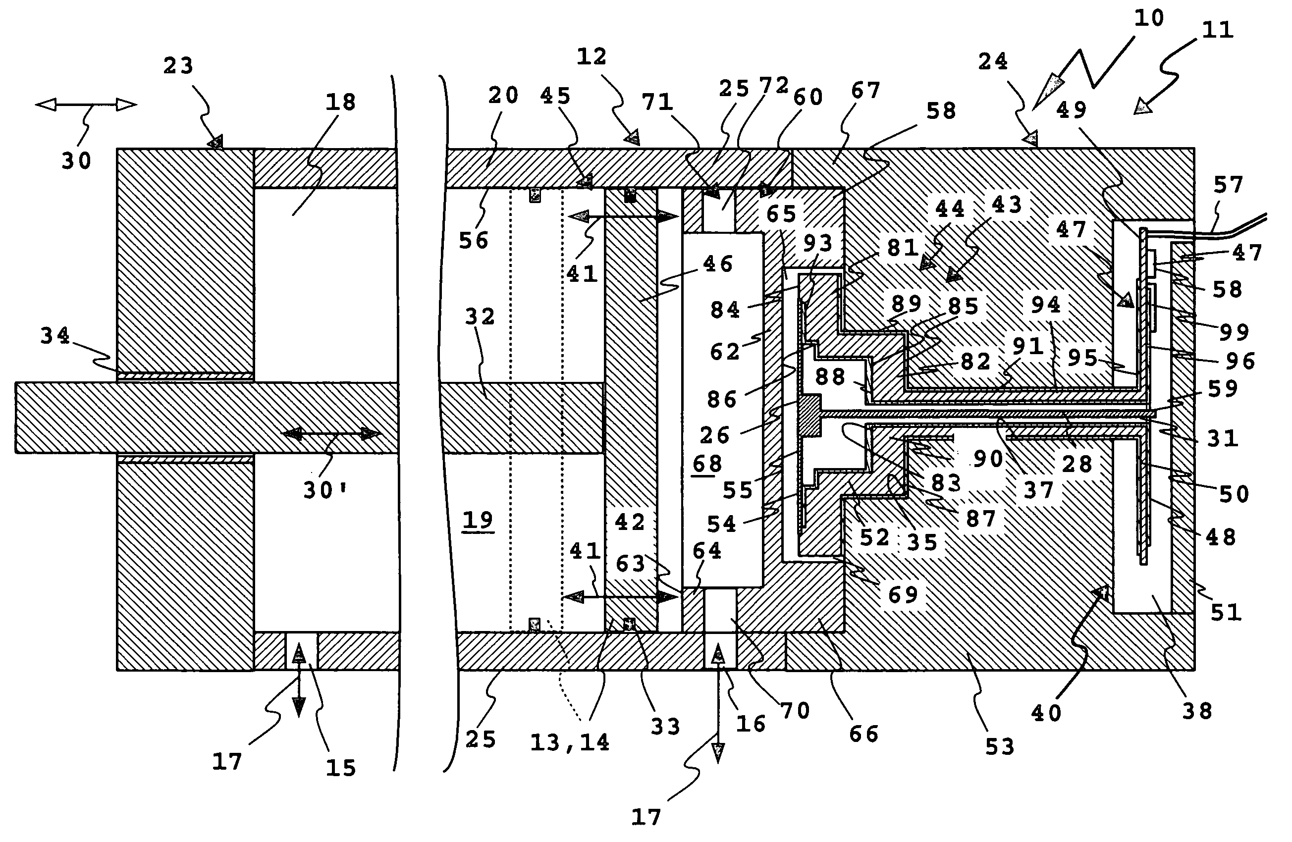
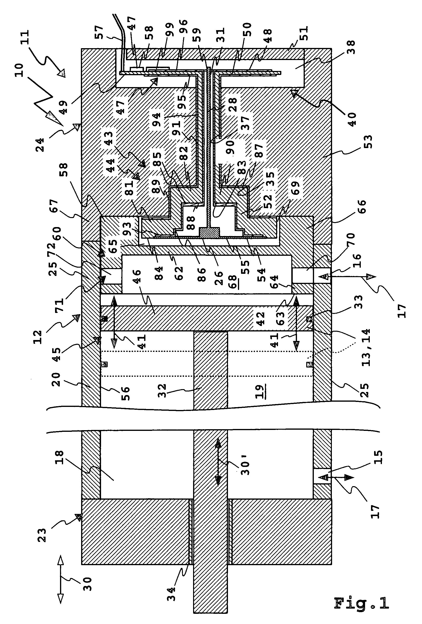
[0049]A pneumatic fluid power cylinder 10 constitutes a servo device 11 and more particularly a fluid power servo device. In a housing 12 a piston 13, forming a servo member 14, is able to reciprocate linearly. By way of fluid or, respectively, compressed air connections 15 and 16 compressed air 17 may flow into and out of a chamber 18, constituting a motion space 19 for the servo member 14 to drive the piston 13.

[0050]A middle part 20 of the housing 12 possessing a peripheral wall 25, for example of metal, is tubular in design and has an internal cross section matching an external outline of the servo member 14 and for example is essentially circular. An end plate 23 with a bearing and a plain end plate 24 or cover, more particularly of metal, at the ends of the housing 12 shut off the chamber 18 in an air tight manner, for example with plain seals, o-ring seals or the like between covers 23 and 24 and the middle part 20. The end plates 23 and 24 are secured in position f. i. by bo...


PUM


Abstract

A position detecting device finds the position of a specimen arranged in a conductive structure on the basis of microwaves and comprises an electrical circuit for the production and / or reception of the microwaves and a microwave antenna arrangement for emitting and / or receiving the microwaves. Said position detecting device includes a dielectric antenna body with a first pole face and a second pole face for the transmission of microwaves. The antenna body forms a component of the microwave antenna arrangement. The electrical circuit is at least in part arranged on the antenna body.

Description

CROSS-REFERENCE TO RELATED APPLICATION[0001]This application claims priority based on European Patent Application No. 05 017 444.0 filed on Aug. 11, 2005, which is incorporated herein by reference.BACKGROUND OF THE INVENTION[0002]1. Field of the Invention[0003]The invention relates to a position detecting device for finding the position of a specimen arranged in a conductive structure on the basis of microwaves, comprising an electrical circuit for producing and / or receiving the microwaves and a microwave antenna arrangement for emitting and / or receiving the microwaves.[0004]2. Description of the Related Art[0005]Such a position detecting device is for example described in the German patent publication DE 102 05 904 A1. The conductive structure is constituted by a housing of a pneumatic cylinder or of a hydraulic cylinder, in which a piston is arranged for longitudinal motion. The position detecting device serves for finding the distance of the piston with respect to a longitudinal ...

Claims


Application Information

Patent Timeline
IPC IPC(8): G01R27/04
CPCF15B15/2869G01S7/003H01Q13/08H01P5/103G01S13/88
Inventor MAIER, MARCUSREININGER, THOMAS
Owner FESTO AG & CO KG
Why Eureka
Try Eureka