Electronic tuner and electronic device

Inactive Publication Date: 2008-05-08
SHARP KK
View PDF6 Cites 8 Cited by
  • Summary
  • Abstract
  • Description
  • Claims
  • Application Information

AI Technical Summary

Benefits of technology

[0028]With this configuration, it is possible to provide an electronic device that is equipped with an electro

Problems solved by technology

However, because the gasket 103, the externally attached spring 104, and the like are relatively expensive components, and a separate step is necessary for installation, these components increase the cost of assembly, and therefore are a primary cause of increased costs.
As described above, in the conventional technology, when establishing grounding reinforcement it is necessary to newly insta

Method used


Image

  • Electronic tuner and electronic device
  • Electronic tuner and electronic device
  • Electronic tuner and electronic device

Examples


embodiment 1

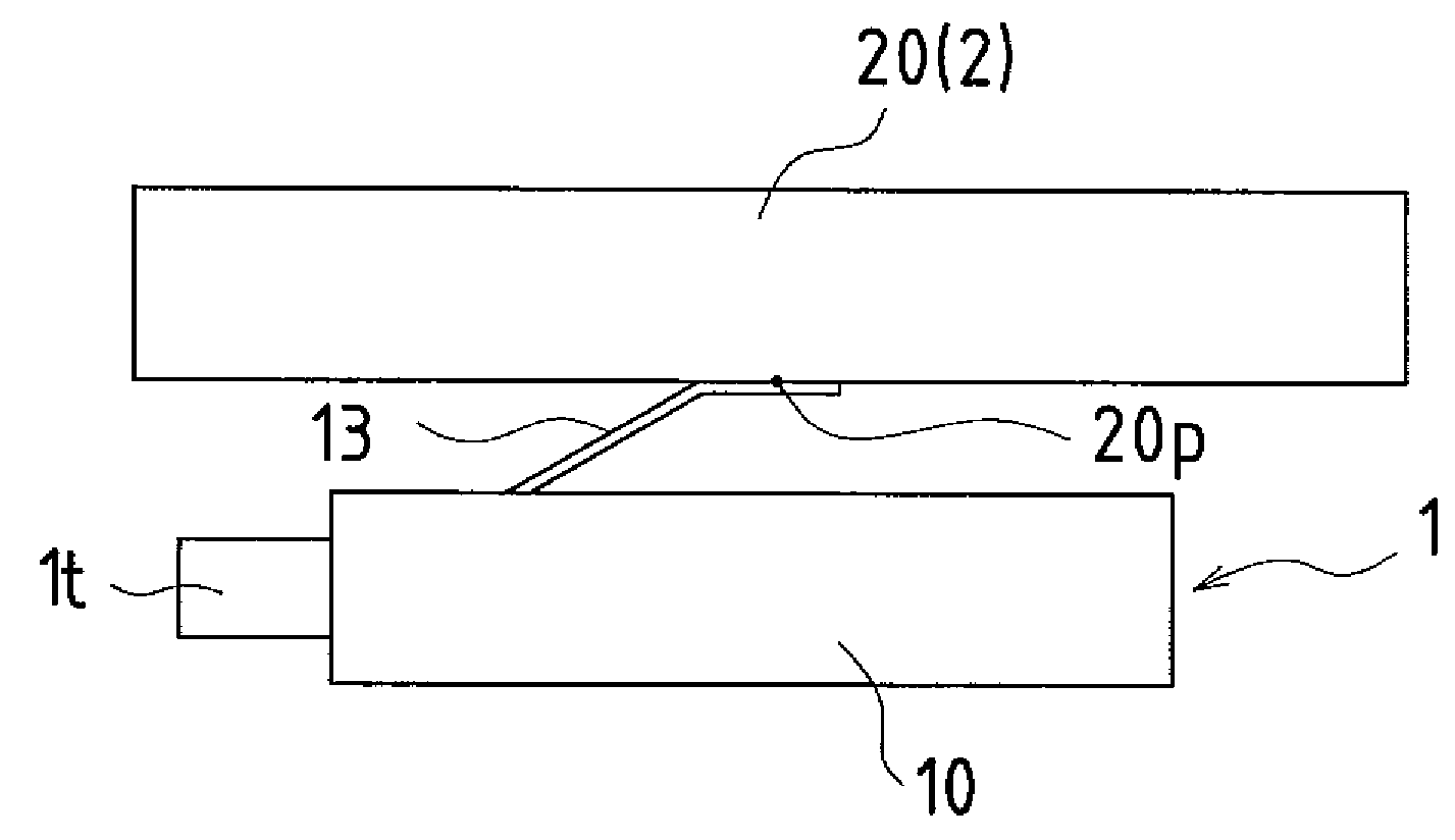
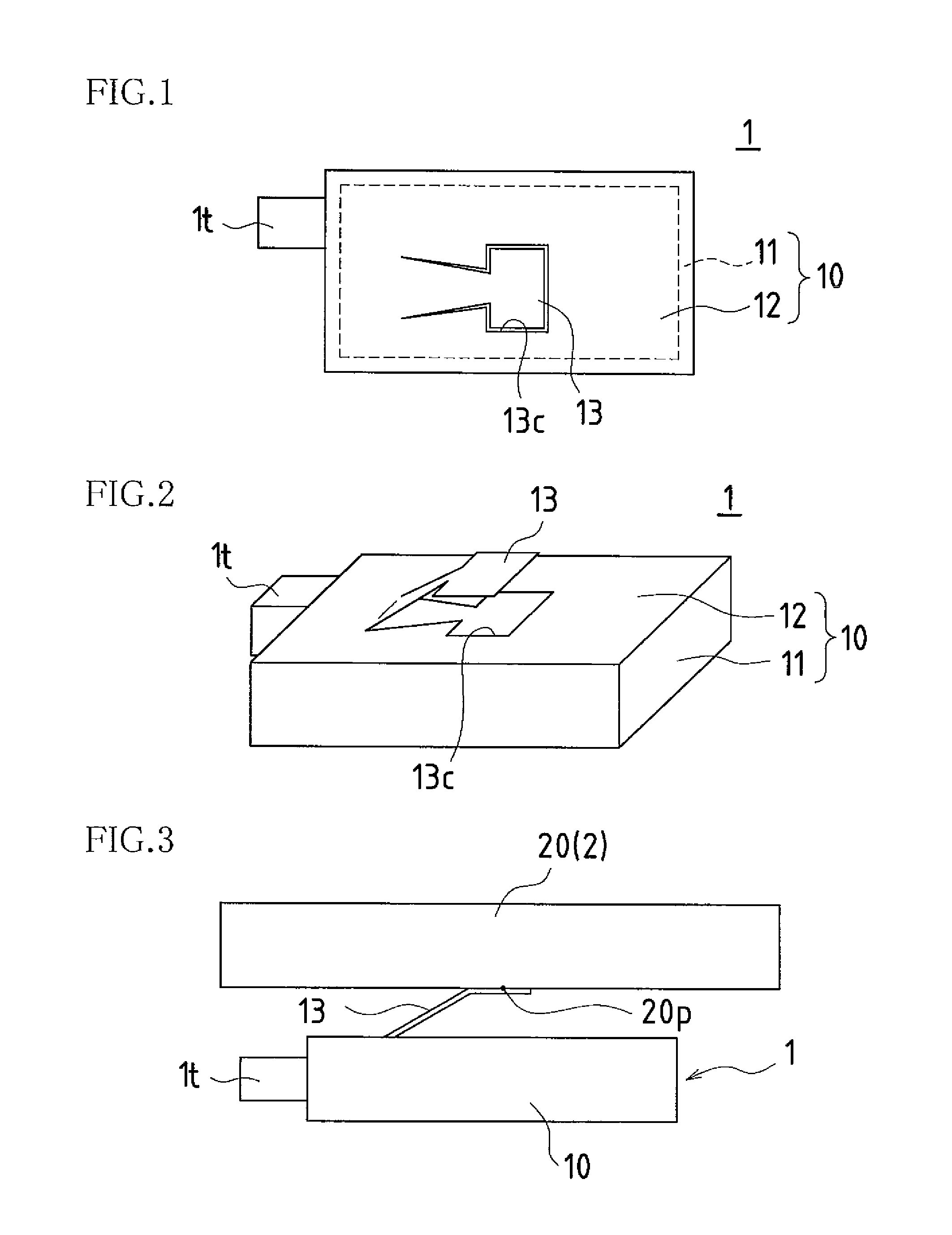
[0042]FIG. 1 is a front view that shows an elastic grounding piece formed in a lid portion of an electronic tuner according to Embodiment 1 of the present invention, and FIG. 2 is a perspective view that shows the elastic grounding piece formed in the lid portion of the electronic tuner according to Embodiment 1 of the present invention. FIG. 3 is a side view that shows a state in which the electronic tuner according to Embodiment 1 of the present invention has been grounded to a device component of an electronic device.

[0043]In an electronic tuner 1 according to the present embodiment, a case 10 is provided. A tuner terminal it is fixed to the case 10, and inside of the case 10 a tuner substrate (not shown) is housed. The case 10 is configured with a frame-like outer circumferential portion 11, and a lid portion 12 that covers a space formed by the outer circumferential portion 11. Also, the case 10 is mounted to an electronic device 2 (a device component 20), and by functioning as...

embodiment 2

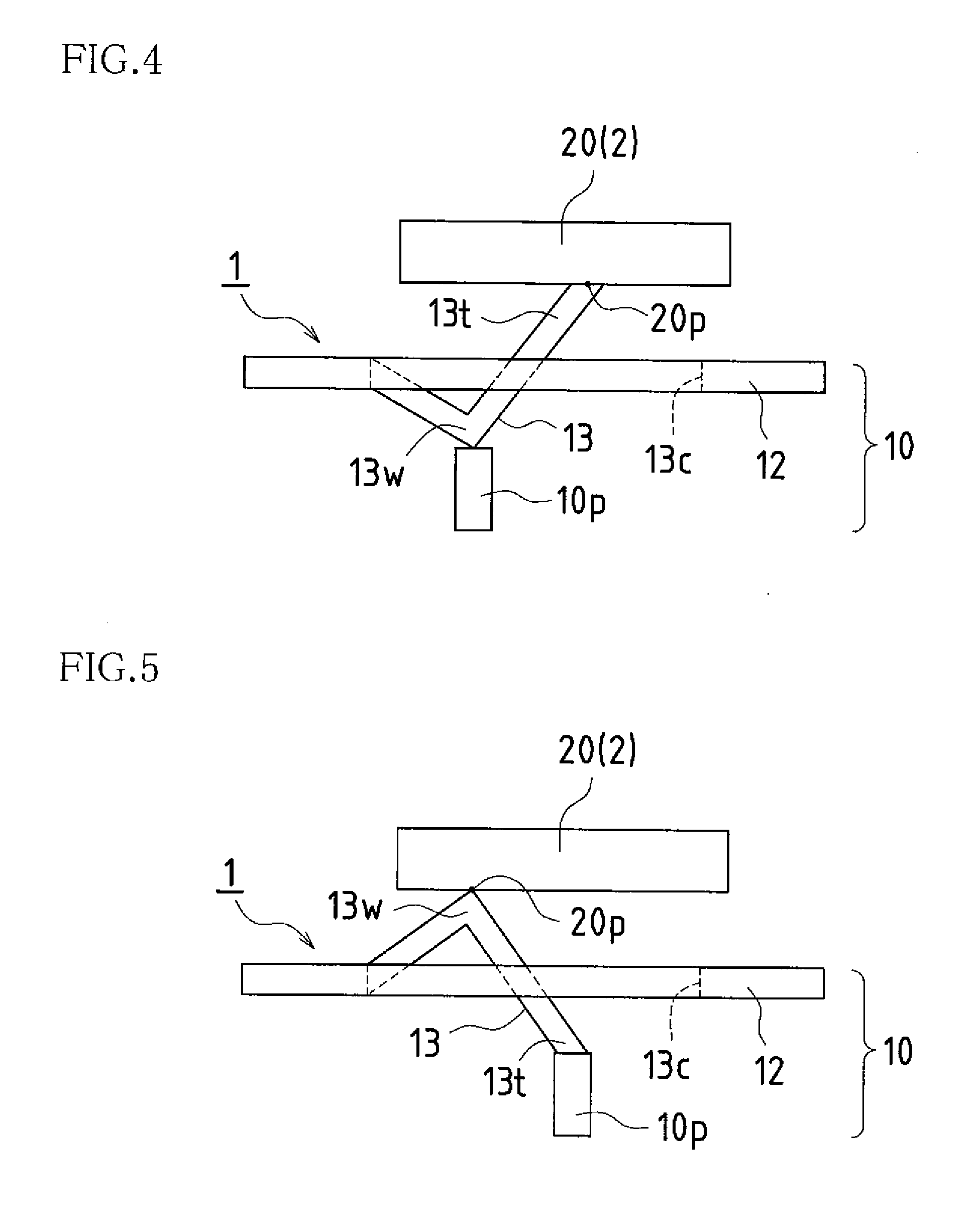
[0049]Embodiment 2 will be described with reference to FIGS. 4 and 5.

[0050]FIG. 4 is an explanatory diagram that illustrates an elastic grounding piece of an electronic tuner according to Embodiment 2 of the present invention, and is a side view that shows a state in which a tip portion of an elastic grounding piece has been grounded to a device component of an electronic device.

[0051]In an elastic grounding piece 13 according to the present embodiment, a bent portion 13w is formed in the middle of the elastic grounding piece 13, which has the shape of a tongue piece. By changing the bend position, it is possible to vary the position where the bent portion 13w is grounded. The basic configuration of the electronic tuner 1 according to the present embodiment is the same as in Embodiment 1, so mainly the differing points will be described here.

[0052]The elastic grounding piece 13 of the electronic tuner 1 shown in FIG. 4 has the bent portion 13w between a tip portion 13t and a base, a...

embodiment 3

[0061]Embodiment 3 will be described with reference to FIGS. 6 to 9.

[0062]FIG. 6 is a side view that shows a state in which an outside tongue piece of an elastic grounding piece of an electronic tuner according to Embodiment 3 of the present invention has been grounded to a device component of an electronic device, and FIG. 7 is an enlarged perspective view that shows an enlargement of the elastic grounding piece of the electronic tuner according to Embodiment 3 of the present invention.

[0063]FIG. 8 is a side view that shows a state in which an inside tongue piece of the elastic grounding piece of the electronic tuner according to Embodiment 3 of the present invention has been grounded to the device component of the electronic device, and FIG. 9 is an enlarged perspective view that shows an enlargement of the elastic grounding piece of the electronic tuner according to Embodiment 3 of the present invention.

[0064]An elastic grounding piece 13 according to the present embodiment has a...


PUM


Abstract

In one embodiment of the present invention, an electronic tuner is provided with a case configured with a frame-like outer circumferential portion and a lid portion that covers a space formed by the outer circumferential portion, and an elastic grounding piece formed by cutting open a portion of the case in the shape of a tongue piece is caused to protrude outside of the case, thus grounding the elastic grounding piece to a grounding portion of an external electronic device.

Description

BACKGROUND OF THE INVENTION[0001]This application claims priority under 35 U.S.C. § 119(a) on Japanese Patent Application No. 2006-301797 filed in Japan on Nov. 7, 2007, the entire contents of which are hereby incorporated by reference.[0002]The present invention relates to an electronic tuner grounded to an electronic device using an elastic grounding piece caused to protrude from a case, and an electronic device equipped with such an electronic tuner.[0003]In an electronic tuner equipped with an electronic device, as a method for suppressing a beat due to noise introduced to the electronic tuner from the electronic device, unnecessary radiation generated from the electronic tuner, or the like, it is known to perform grounding reinforcement at an appropriate location between the electronic tuner and the electronic device. A conventional example of a means for performing grounding reinforcement is described below with reference to FIGS. 11 and 12.[0004]FIG. 11 is a side view that il...

Claims


Application Information

Patent Timeline
IPC IPC(8): H05K9/00
CPCH05K9/006
Inventor KATAGIRI, YOSHITAKA
Owner SHARP KK
Why Eureka
Try Eureka