
High frequency self-lock connector

a high-frequency, self-locking technology, applied in the direction of coupling device connection, two-part coupling device, electrical apparatus, etc., can solve the problems of slow connection speed, inability to realize quick connection and high density arrangement, poor electrical property and vibration resistance of such poor devices, etc., to achieve fast and reliable connection, small space, good mechanical

Inactive Publication Date: 2008-05-08
AVIC FORSTAR S&T CO LTD
View PDF9 Cites 10 Cited by
  • Summary
  • Abstract
  • Description
  • Claims
  • Application Information

AI Technical Summary

Benefits of technology

The present invention provides a high frequency push-in type quick self-lock connector that has good vibration resistance, quick connection, small VSWR, and higher stability. The connector has a plug and a socket that can be easily connected and disconnected. The plug has a plug housing and a plug inner conductor, while the socket has a socket housing and a socket inner conductor. The plug inner conductor is in tight contact with the socket inner conductor when connected. The connector is convenient to use and has a low cost.

Problems solved by technology

The threaded connection is characterized by high and good electrical property, but it has a slow connection speed and requires a sufficient surrounding space so that it is impossible to realize quick connection and high density arrangement.
The plug-in and bayonet connections both have quick connection speed, but electrical property and vibration resistance thereof are too poor to be used in high demanding applications.
The push-in type self-lock connection is characterized by quick connection and high reliability, but with conventional push-in type self-lock connectors, the connection interface configuration is complicated and tolerance accumulation of many dimensions renders a great variation in electrical length of the connector interface, and therefore, they have a high cost and can not be used in a system requiring good electrical property.

Method used


Image

  • High frequency self-lock connector
  • High frequency self-lock connector
  • High frequency self-lock connector

Examples


Embodiment Construction

[0060]The present invention will be described in detail with reference to the embodiments. The examples thereof are shown in the figures. Throughout the drawings, the same reference numerals designate the same elements or parts. The embodiment is described in conjunction with the drawings in order to explain the present invention

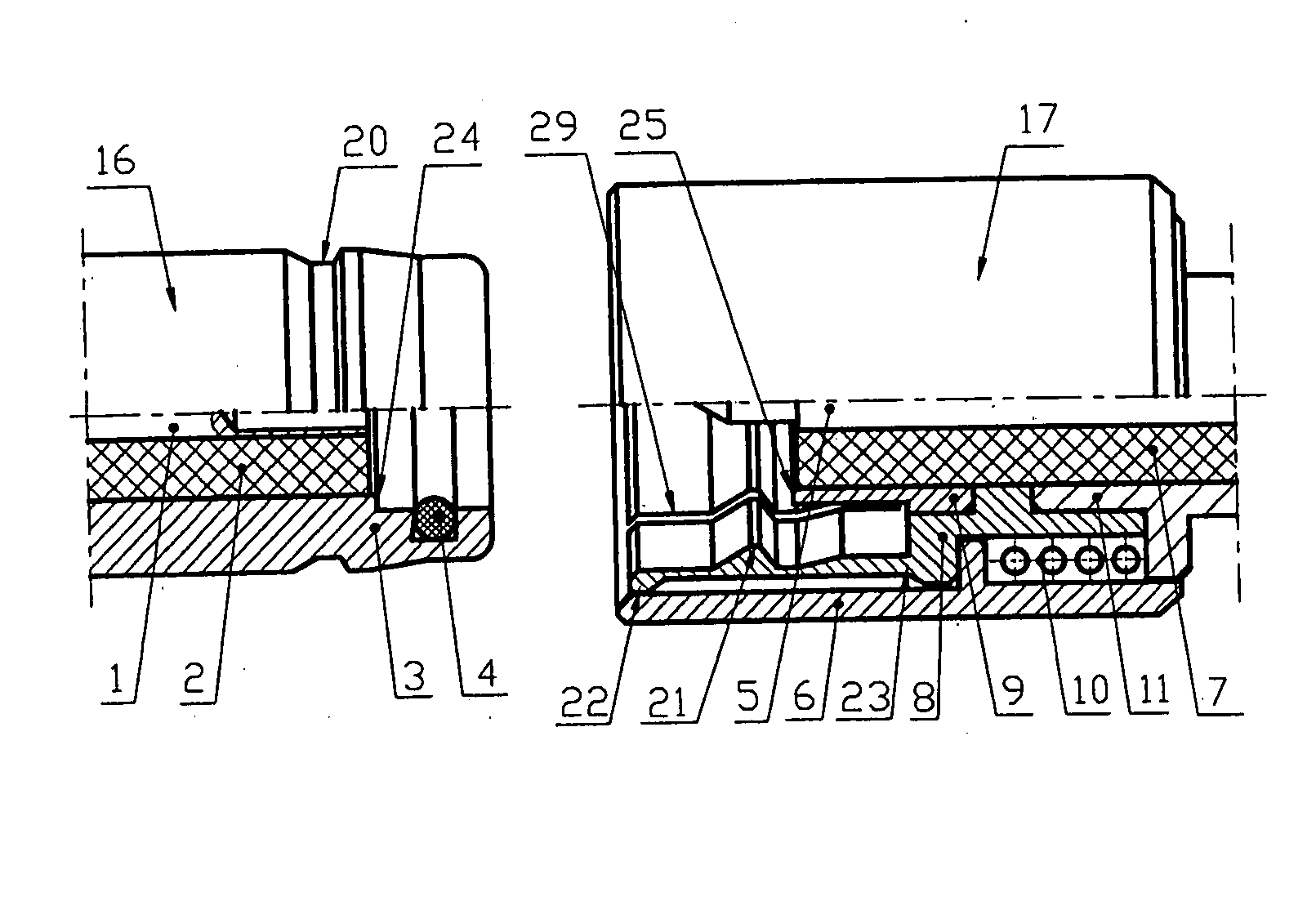
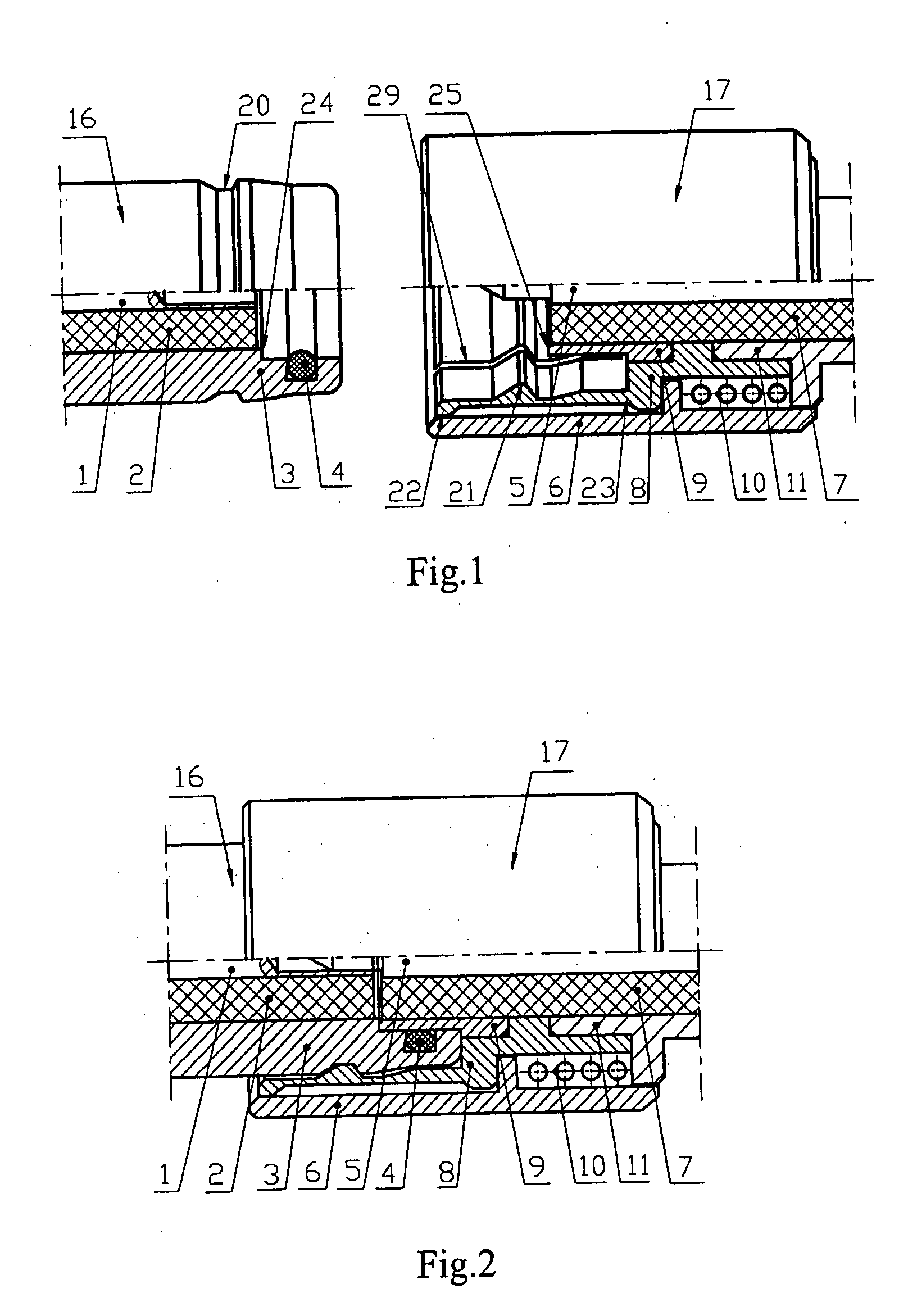
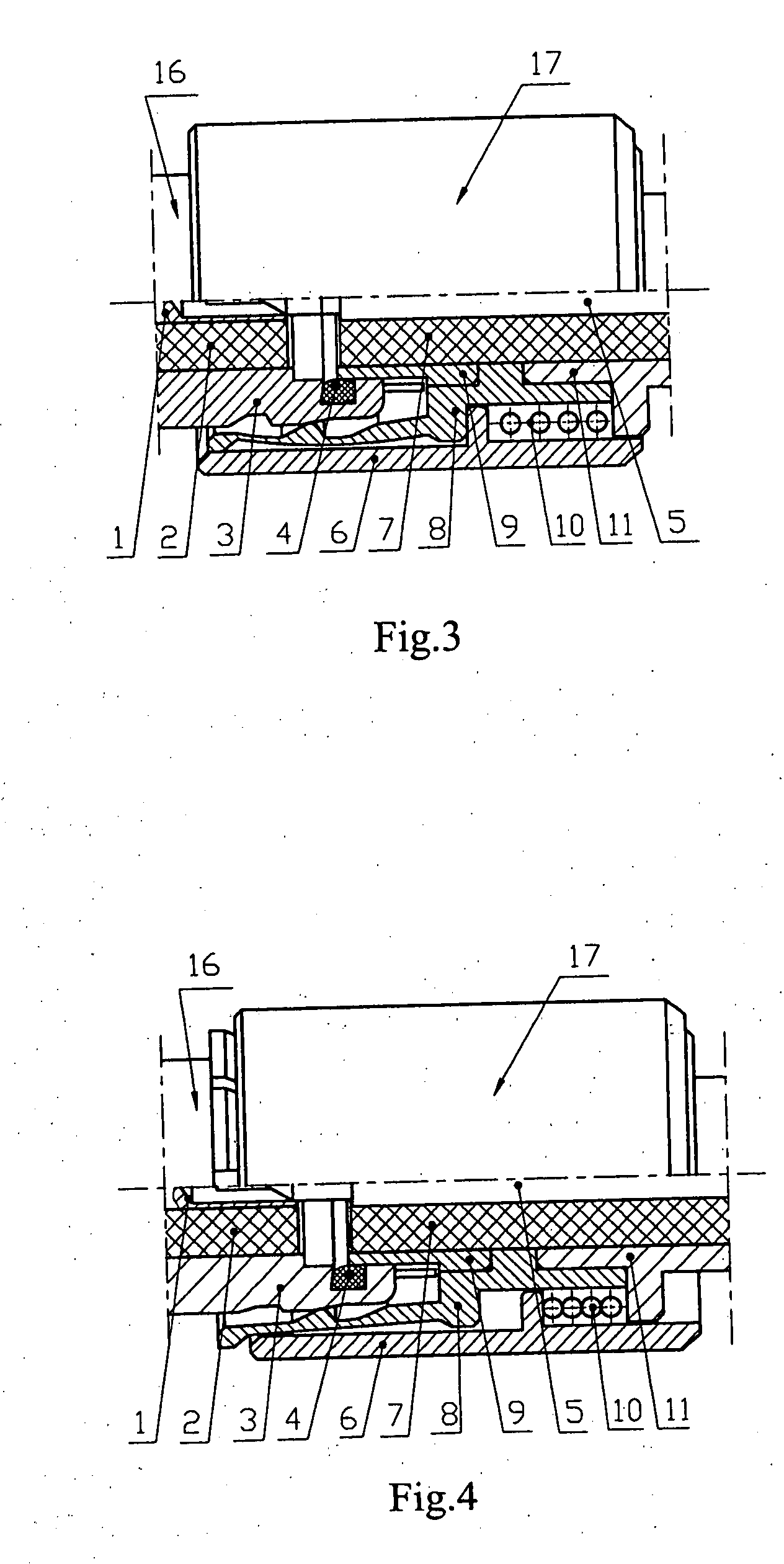
[0061]FIGS. 1-5 shows the first embodiment of the high frequency self-lock connector according to the present invention. As shown in FIGS. 1-5, the connector comprises a socket 16 and a plug 17. The plug 17 has a plug housing 11 and a plug inner conductor 5. The socket 16 has a socket housing 3 and a socket inner conductor 1. The plug 17 may be inserted into the socket 16 in an axial direction. The plug 17 further comprising a plug sleeve 6 connected with the plug housing 11 via an elastic member 10. A first contact member 8 is disposed within the plug sleeve 6. The plug sleeve 6 serves to protect the first contact member 8 and control the locking elastic fo...


PUM


Abstract

The present invention relates to a high frequency self-lock connector, comprising a plug and a socket (16), wherein the plug (17) further comprising a plug sleeve connected with the plug housing (11) via an elastic member (10); a first contact member (8) is disposed within the plug sleeve (6); the first contact member (8) is fixed with respect to the plug housing (11); the first contact member (8) clamps the socket housing (3); a second contact member (9) is fixed on the plug housing (11) and connected with the first contact member (8) via the plug housing (11); the second contact member (9) abuts on an inner step of the socket housing (3); and the plug inner conductor (5) is in tight contact with the plug inner conductor (1). The connector of the present invention has a high vibration resistance, stable phase, quick connection, small SWR and good stability and is convenient for use.

Description

FIELD OF THE INVENTION[0001]The present invention relates to a RF coax connector for microwave transmission. Specifically, the present invention relates to a high frequency push-in type quick self-lock connector.BACKGROUND OF THE INVENTION[0002]RF coax connectors serve to connect coax transmission lines, microstrip circuits and PCB circuits in microwave transmission circuits. Since RF coax connectors have the advantages that they have a wide working frequency band and provide a convenient connection and a high reliability, they are widely used in the field of aerospace and aviation systems, microwave communication engineering, and military and arms industry. RF coax connectors have a variety of connection means depending on applications, typically including threaded connection, bayonet connection, plug-in connection and push-in type self-lock connection. The threaded connection is characterized by high and good electrical property, but it has a slow connection speed and requires a s...

Claims


Application Information

Patent Timeline
Patent Type & Authority Applications(United States)
IPC IPC(8): H01R4/26
CPCH01R13/6277H01R2103/00H01R24/40
Inventor WU, XIANGWENZHANG, GANGZHUYANG, QIULIZHANG, JINGLIANG
Owner AVIC FORSTAR S&T CO LTD
Learn More