Radio base station, relay station and radio communication method

a radio communication and relay station technology, applied in the field of radio communication methods, can solve the problems of difficult radio connection with affecting the operation of the radio base station, so as to prevent the degradation of the transmission efficiency otherwise degrading, efficient use, and the effect of smooth management of the radio terminal

Inactive Publication Date: 2008-05-08
FUJITSU LTD
View PDF38 Cites 42 Cited by
  • Summary
  • Abstract
  • Description
  • Claims
  • Application Information

AI Technical Summary

Benefits of technology

[0066] According to the present invention, it is possible to provide the system and the procedure in which the relay station can be efficiently used.
[0067] Further, according to the present invention, management of the radio terminal by the radio base station can be made smoothly even with the existence of the relay station.
[0068] Further, according to the present invention, it is possible to prevent degradation in the transmission efficiency otherwise degrading due to a fact that a radio communication environment between the radio base station and the relay station may not necessarily equal to that between the relay station and the radio terminal.

Problems solved by technology

However, even within the service area in which the radio base station can carry out radio communication, high speed communication may not be available in a place close to the area boundary, since the radio environment may not be satisfactory.
Further, even within the area, radio signal propagation may be obstructed by a cause such as a building shade.
Thus, an area (so-called dead zone) in which satisfactory radio connection with the radio base station is difficult may occur.

Method used


Image

  • Radio base station, relay station and radio communication method
  • Radio base station, relay station and radio communication method
  • Radio base station, relay station and radio communication method

Examples


first embodiment

[a] Description of First Embodiment

[0086] In a first embodiment of the present invention, a relay station transmits a signal after processing a signal received from a radio terminal, to a radio base station.

[0087] In this configuration, the relay station positively functions in communication between the radio terminal and the radio base station. For example, a signal which is not necessarily required to be transmitted to the radio base station is not transmitted to the radio base station. Thus, management of the radio terminal by the radio base station can be carried out smoothly. Further, signal processing which can be carried out by the relay station is carried out by the relay station itself. Accordingly, it is possible to reduce a processing load of the radio base station. Further, the radio base station can manage as to which relay station is used by the radio terminal.

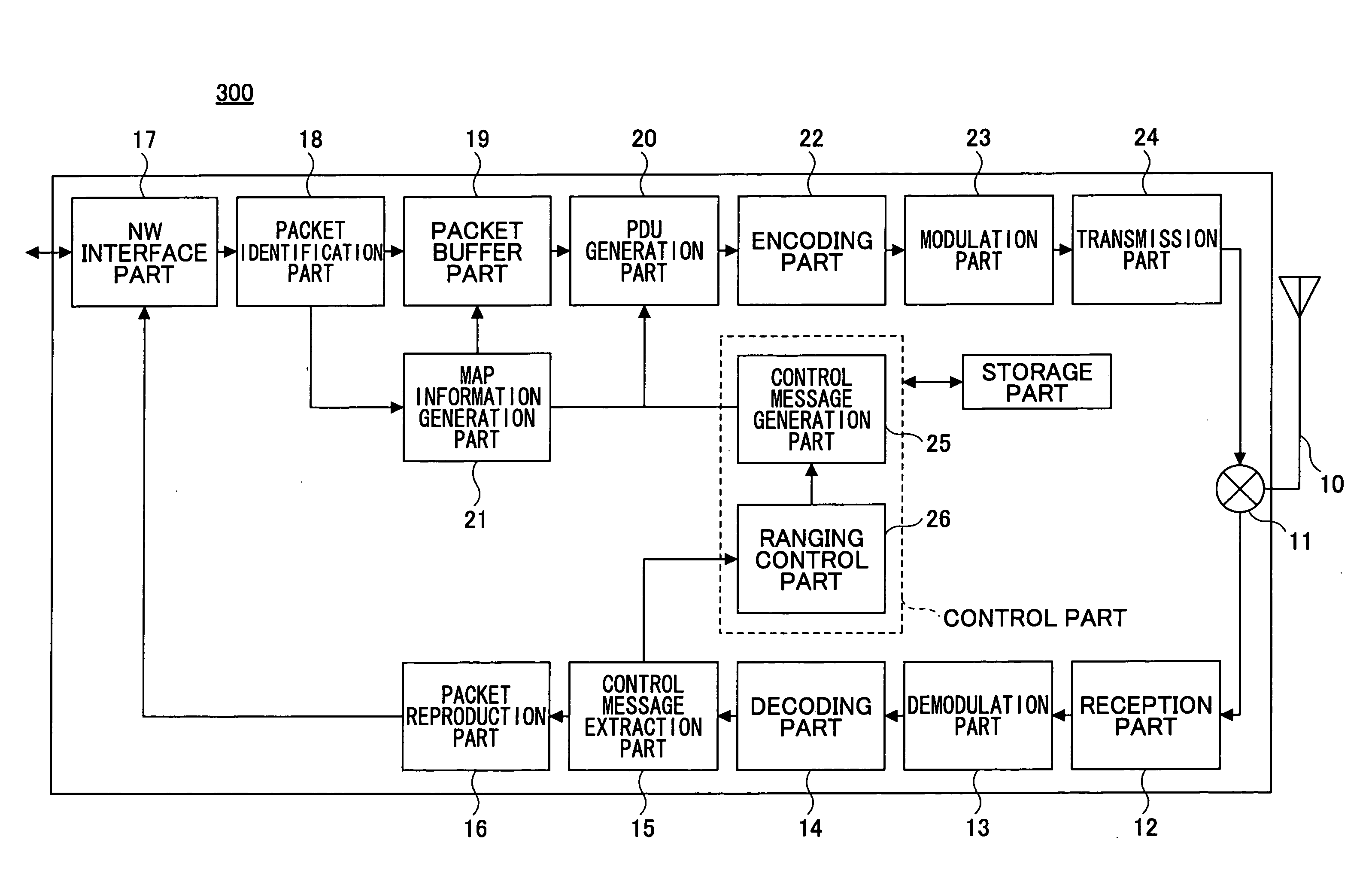
“Basic System Configuration”:

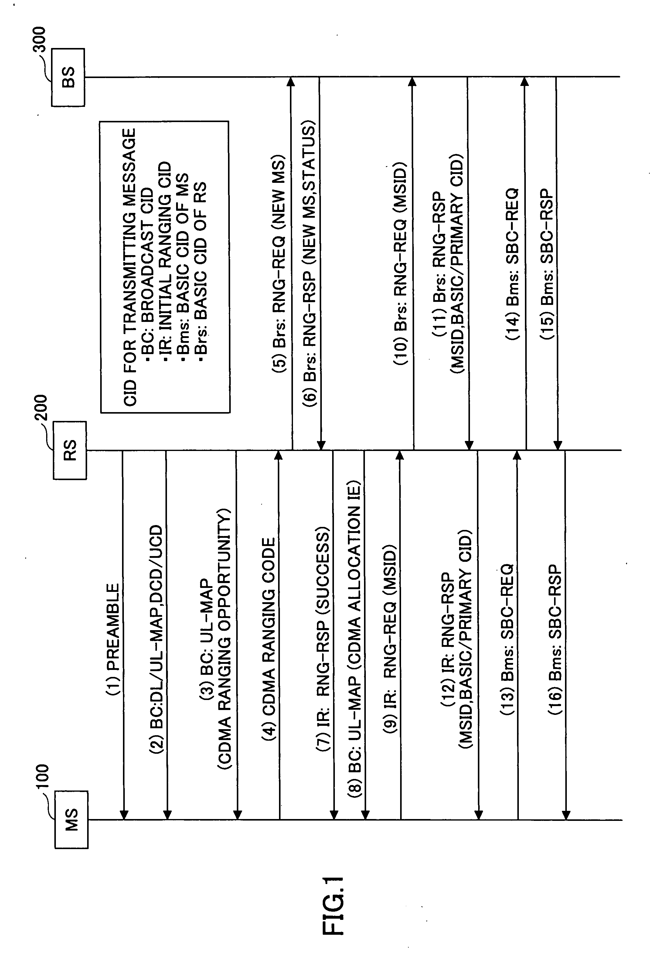
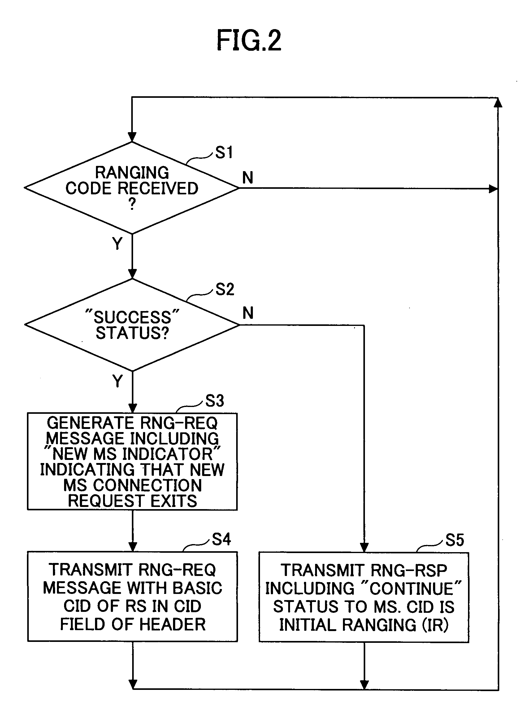
[0088]FIG. 1 shows a processing sequence for a case where the relay station is...

second embodiment

[b] Description of Second Embodiment

[0192] In the first embodiment described above, the RS 200 itself generates the MAP data, and transmits it to the MS 100. However, in a second embodiment of the present invention, which will now be described, the BS 300 generates the MAP data which the RS 200 transmits to the MS 100, and transmits it via the MMR link. Thus, the RS 200 transmits the MAP data, having been received from the BS 300, as MAP data which the RS 200 itself is to transmit.

[0193] Thereby, the RS 200 can leave scheduling processing in the charge of the BS 300, and thus, a processing load of the RS 200 can be reduced, whereby the apparatus of the RS 200 can be miniaturized.

[0194]FIG. 9 shows a ranging and basic capability registration sequence for the MS 100 to start connection with the RS 200.

[0195] In comparison with FIG. 1, it is seen that, the MAP data (3), (5) and (11), corresponding to the messages (2), (3) and (8) of FIG. 1, are transmitted based on the MAP data (2),...

third embodiment

[c] Description of Third Embodiment

[0238] In a third embodiment of the present invention, degradation in the transmission efficiency, otherwise occurring due to a fact that a radio communication environment between the BS and the RS and a radio communication environment between the RS and the MS may not be identical to one another can be controlled.

[0239] It is noted that, in this embodiment, one example of an authentication sequence is described, which may be carried out subsequent to the ranging and basic capability registration sequence described above for the first and second embodiments.

[0240]FIG. 15 shows the authentication sequence which should be preferably carried out after the end of the ranging and basic capability registration sequence.

[0241] In this embodiment, the MS 100 carries out the authentication sequence after finishing the ranging and basic capability registration sequence.

[0242] First, the MS 100 transmits its own authentication data (for example, an electr...


PUM


Abstract

A relay station has a reception unit receiving a signal sequence indicating a connection request, from among a predetermined signal sequence group; a control unit generating a ranging request message indicating that a radio terminal newly requesting connection exists; and a transmission unit transmitting the ranging request message to a radio base station.

Description

BACKGROUND OF THE INVENTION [0001] 1. Field of the Invention [0002] The present invention relates to a radio base station, a relay station, using radio communication, and a radio communication method. The present invention is especially advantageous when it is applied to a case where a radio communication system prescribed by IEEE802.16 is used as a base system and thereto a relay station is added. [0003] 2. Description of the Related Art [0004] A radio communication system carrying out communication with the use of a radio channel, i.e., WCDMA, CDMA2000 or such, as a typical example, currently spreads worldwide. In such a radio communication system, a plurality of radio base stations are set for a service area, and each radio terminal carries out communication with another communication apparatus (i.e., another communication terminal) with the use of any of the radio base stations. At this time, an overlapping area is provided with an adjacent service area in which an adjacent base...

Claims


Application Information

Patent Timeline
Patent Type & Authority Applications(United States)
IPC IPC(8): H04B7/185H04B3/36H04W16/26
CPCH04B7/155H04B7/2606H04B7/15H04W84/047H04W74/0883
Inventor OKUDA, MASATO
Owner FUJITSU LTD
Why Eureka
Try Eureka