Golf club head and method of fabricating striking plate
a technology of striking plate and golf club head, which is applied in the field of golf club head and a method of fabricating striking plate, can solve the problems of reducing the durability of striking plate, affecting the performance of striking plate, and affecting the durability of striking plate, so as to achieve the effect of enhancing the high-cor region of striking plate and reducing the durability of plate body
- Summary
- Abstract
- Description
- Claims
- Application Information
AI Technical Summary
Benefits of technology
Problems solved by technology
Method used
Image
Examples
first embodiment
The First Embodiment
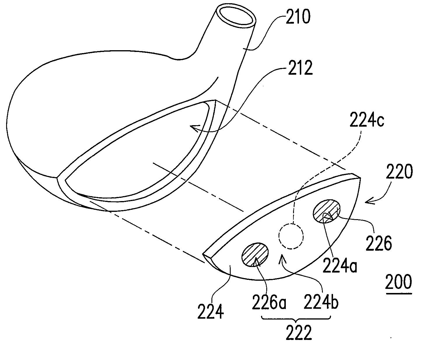
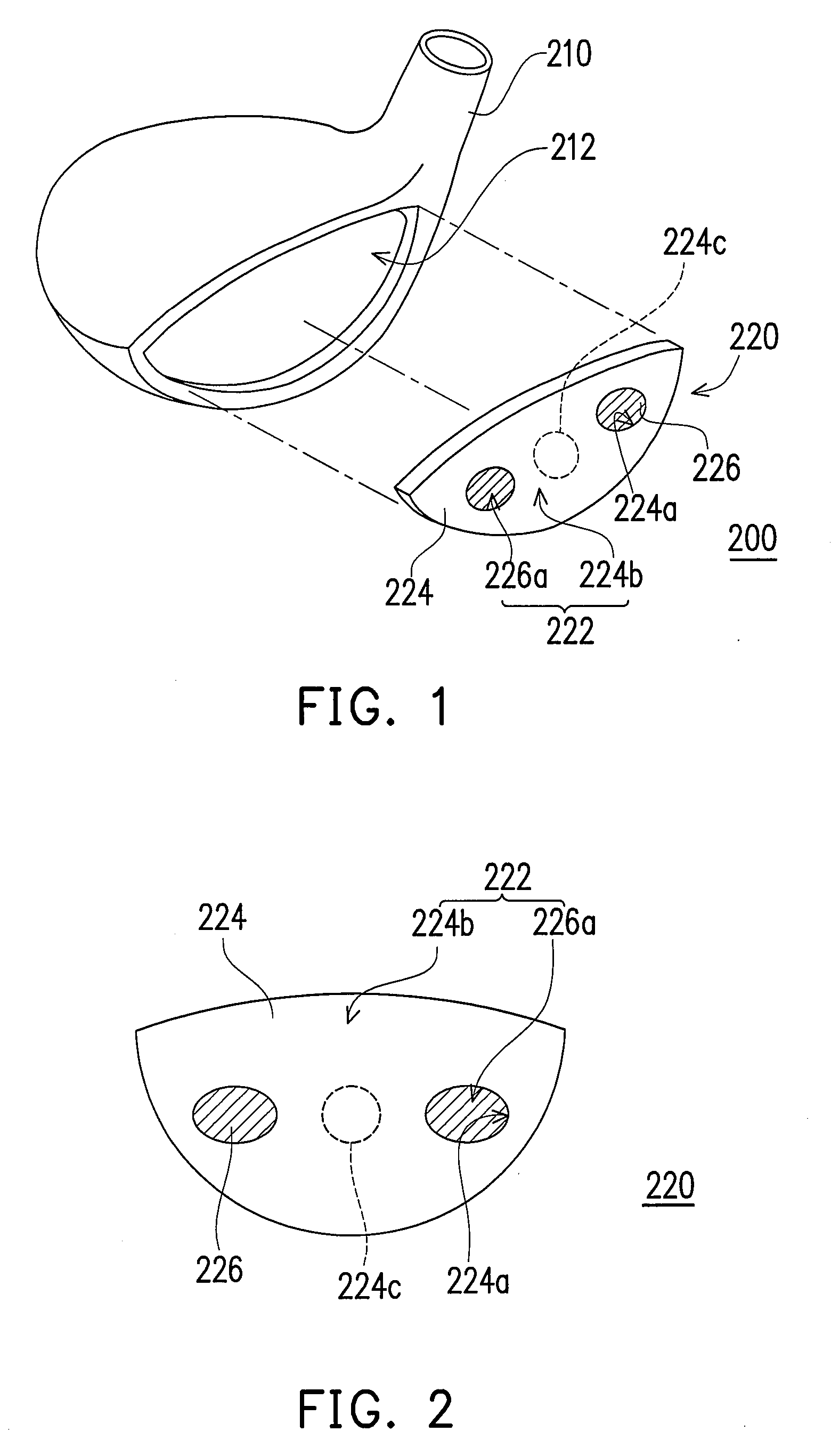
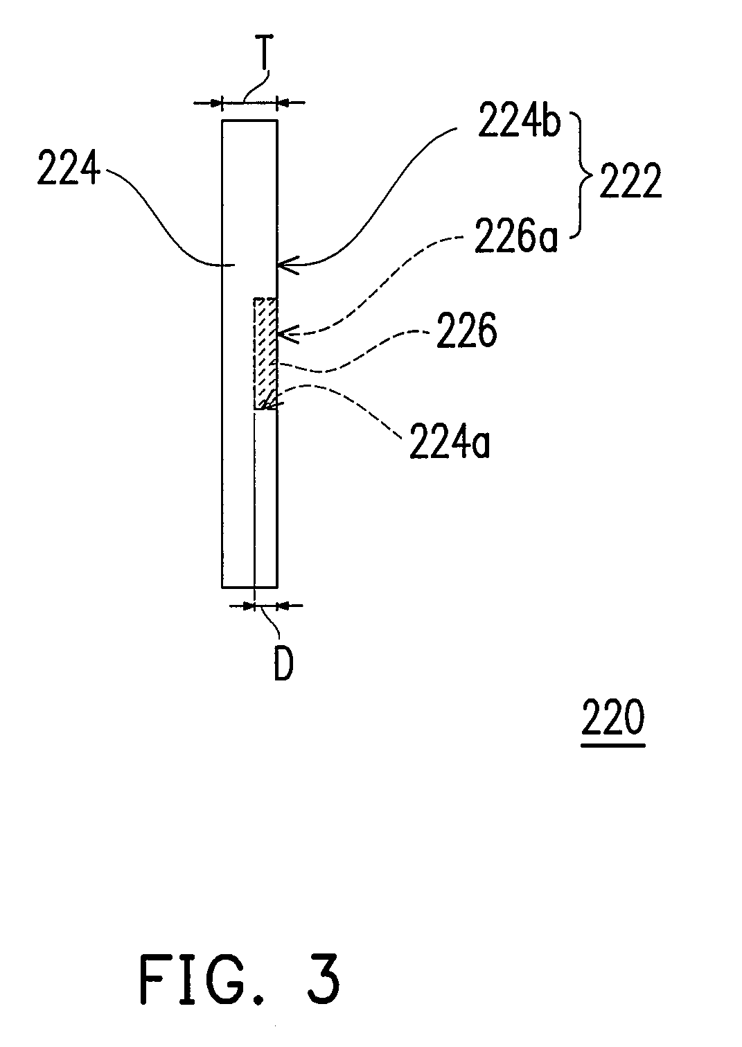
[0053]FIG. 1 is a schematic 3D exploded view of a golf club head according to a first embodiment of the present invention. Referring to FIG. 1, the golf club head 200 includes a head body 210 and a striking plate 220. The head body 210 has an opening 212, and the striking plate 220 is disposed at the opening 212. The head body 210 and the striking plate 220 form the golf club head 200. In the embodiment, the head body 210 may be a shell, and integrally formed by a common metal material (e.g., stainless steel) by way of lost-wax casing.
[0054]Obviously, the head body 210 in other embodiments of the present invention may also be made of a composite material of metal and a macromolecule plastic material or a high-strength fiber material (for example, carbon fiber) and fabricated by the following steps. For example, a crown (not shown) is independently made by injection molding or thermal compression molding in advance. Then, the crown is embedded into another part of...
second embodiment
The Second Embodiment
[0066]FIG. 5 is a schematic side view of a striking plate according to a second embodiment of the present invention. The major difference between the striking plate 320 in the second embodiment and the striking plate 220 in the first embodiment is that the striking plate 320 of the second embodiment has no cavities 224a. The low-elastic-modulus regions 326 are disposed in the plate body 324 by a penetrating process. The depth D′ of each low-elastic-modulus region 326 may be smaller than 2 mm.
[0067]FIGS. 6A to 6D are schematic flowcharts illustrating the process of fabricating the striking plate in FIG. 5. First, referring to FIG. 6A, a plate body 324 with a first surface 324b is provided. Next, referring to FIG. 6B, a low-elastic-modulus material M is disposed on at least a part of the first surface 324b.
[0068]Next, referring to FIG. 6C, the low-elastic-modulus material M is heated and melted by irradiating the low-elastic-modulus material M with, for example, ...
PUM
| Property | Measurement | Unit |
|---|---|---|
| elastic modulus | aaaaa | aaaaa |
| elastic modulus | aaaaa | aaaaa |
| depth | aaaaa | aaaaa |
Abstract
Description
Claims
Application Information
 - R&D
- Intellectual Property
- Life Sciences
- Materials
- Tech Scout
- Unparalleled Data Quality
- Higher Quality Content
- 60% Fewer Hallucinations
Browse by: Latest US Patents, China's latest patents, Technical Efficacy Thesaurus, Application Domain, Technology Topic, Popular Technical Reports.
© 2025 PatSnap. All rights reserved.Legal|Privacy policy|Modern Slavery Act Transparency Statement|Sitemap|About US| Contact US: help@patsnap.com


