Dialysis Catheter
a catheter and catheter technology, applied in the field of catheters, can solve the problems of complicated dissection, neck certainly is not the unobtrusive location, doctor's limitations on the distance between the distal tip of the catheter and the cuff, etc., and achieve the effect of preventing bleeding and facilitating catheter replacemen
- Summary
- Abstract
- Description
- Claims
- Application Information
AI Technical Summary
Benefits of technology
Problems solved by technology
Method used
Image
Examples
first embodiment
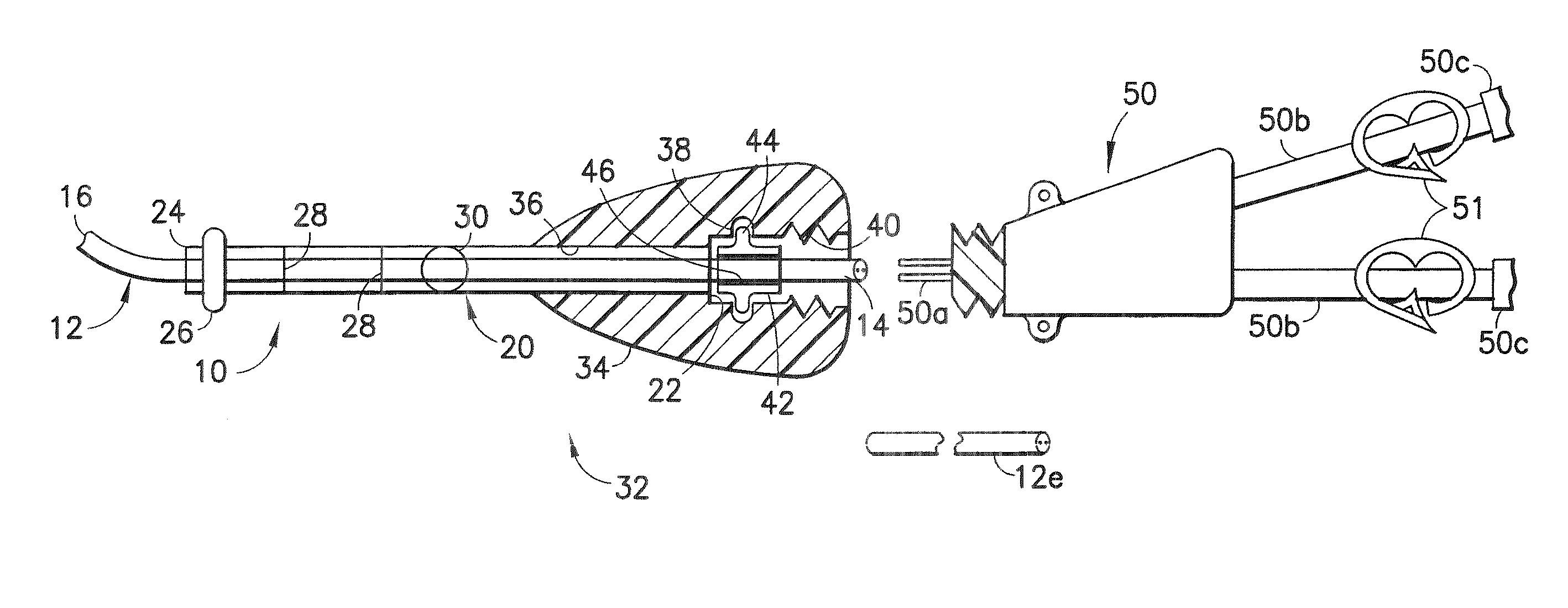
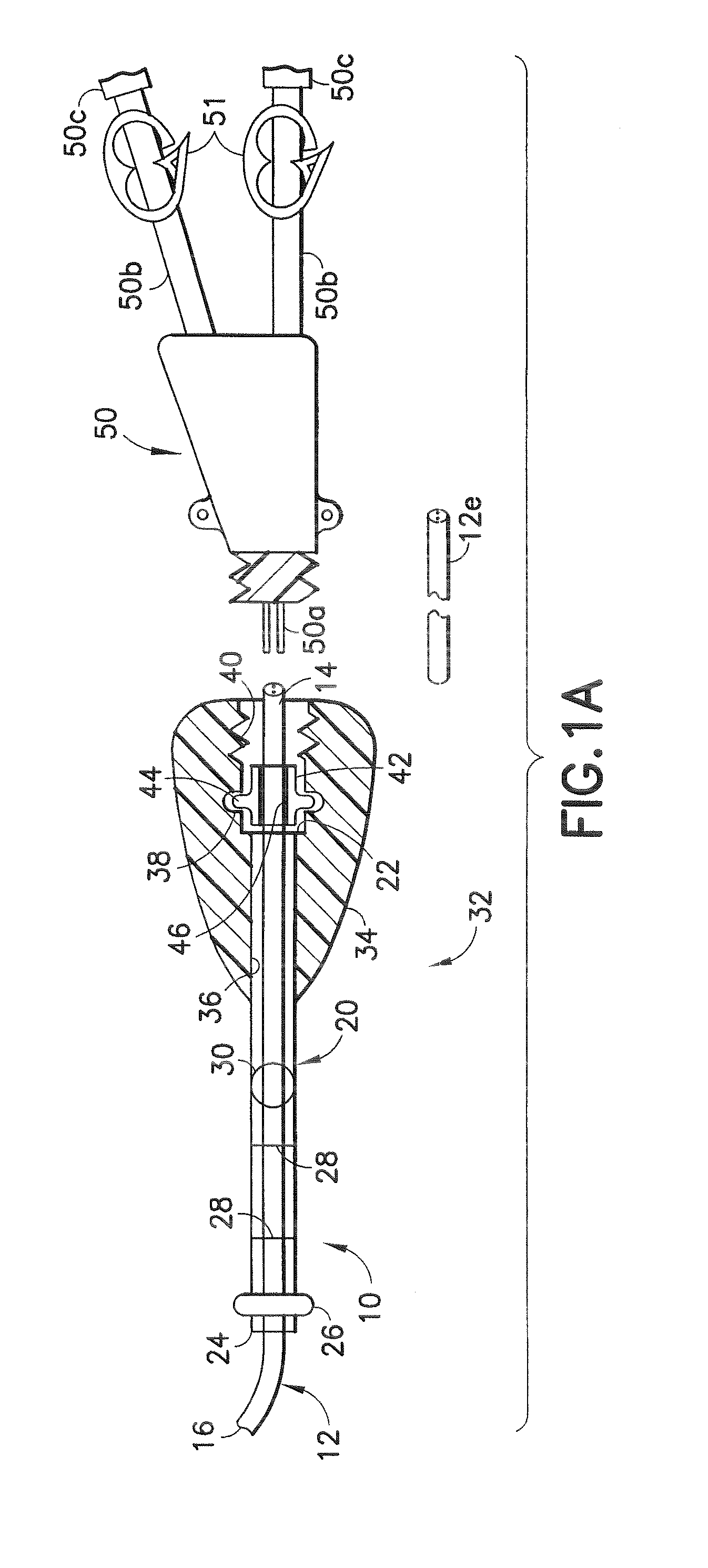
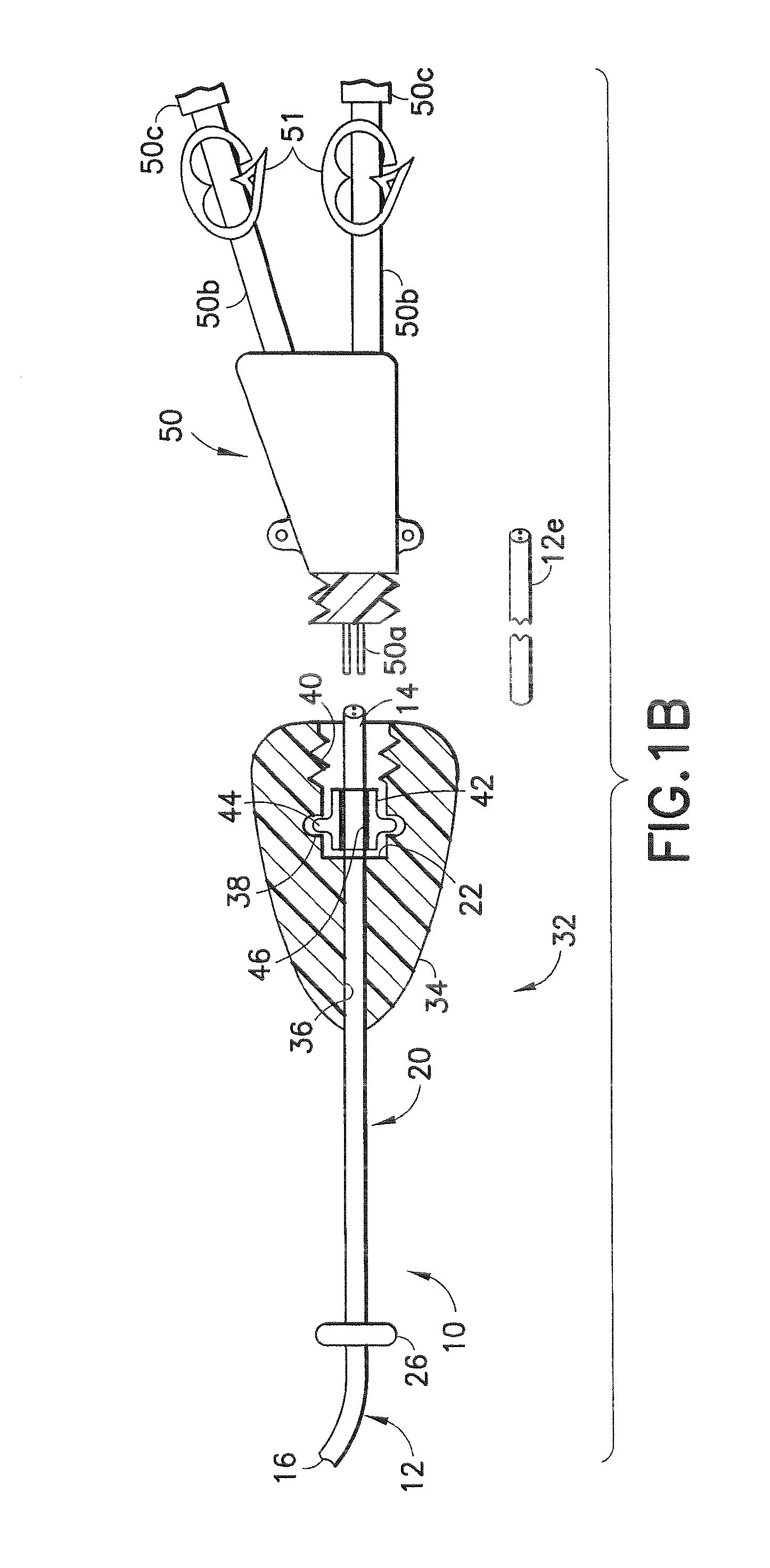
[0061] A dialysis catheter assembly in accordance with the invention is identified generally by the numeral 10 in FIG. 1A. The catheter assembly 10 includes a catheter 12 with a proximal end 14 and a distal end 16. The proximal end 14 will be disposed externally on the patient, while the distal end 16 will be positioned at a selected location in a blood vessel of the patient, and preferably in close proximity to the heart of the patient. A subcutaneous tube 20 is mounted over a portion of the catheter 12 near the proximal end 14. The subcutaneous tube 20 will be disposed in a subcutaneous tunnel extending from a location on the chest of the patient to a location near the neck of the patient. The tube 20 includes a proximal end 22 that will be disposed externally of the patient and a distal end 24 that will be in the subcutaneous tunnel. A polyester cuff 26 or other fibrosing agent is disposed near the distal end of the tube 24 and is configured to promote the growth of scar tissue t...
second embodiment
[0067] A catheter in accordance with the invention is identified by the numeral 62 in FIG. 7. The catheter 62 includes a proximal end 64 and a distal end 66. Portions of the catheter 62 adjacent the proximal end 64 are formed with non-cylindrical external surface configurations 68. In a preferred embodiment, as shown in FIG. 7, the exterior of the catheter 62 near the proximal end 64 includes an alternating arrangement of conical surfaces 68A intersecting radial surfaces 68B. Thus, a Christmas tree pattern is formed. The catheter 62 is used with a hub 70, as shown in FIG. 8. The hub 70 has a proximal end 72, a distal end 74 and a passage 76 extending therebetween. The passage 76 includes surface configurations that mate with the external surface configuration 68 near the proximal end 64 of the catheter 62. As a result, the proximal end 64 of the catheter 62 can be urged in a distal-to-proximal direction into the distal end 74 of the hub 70. This distal-to-proximal movement of the ca...
third embodiment
[0069] a hub in accordance with the subject invention is identified generally by the numeral 80 in FIG. 9. The hub 80 has a proximal end 82, a distal end 84 and a passage 86 extending therethrough. A notch 88 is formed on the outer surface of the hub 80 near the distal end 84. A cuff 90, as shown in FIG. 10, can be pressed over the distal end 84 of the hub 80 and forcibly retained in the notch 88 to compress the hub 80 into engagement with the catheter 12. This assembly can be used substantially as with the previous embodiments and ensures that the distal end 16 of the catheter 12 can be positioned precisely and that the cuff 90 can be disposed at the preferred position for anchoring in the tunnel.
PUM
 Abstract
Description
Claims
Application Information
 - R&D
- Intellectual Property
- Life Sciences
- Materials
- Tech Scout
- Unparalleled Data Quality
- Higher Quality Content
- 60% Fewer Hallucinations
Browse by: Latest US Patents, China's latest patents, Technical Efficacy Thesaurus, Application Domain, Technology Topic, Popular Technical Reports.
© 2025 PatSnap. All rights reserved.Legal|Privacy policy|Modern Slavery Act Transparency Statement|Sitemap|About US| Contact US: help@patsnap.com


