Mounting Devices for Fixation Devices and Insertion Instruments Used Therewith

a technology of fixing device and mounting device, which is applied in the field of bone implants, can solve the problems of weakening the connection, loosening and playing at the interface between the surface and bone material, and weakening the attachment to the bon

Active Publication Date: 2008-05-08
PIONEER SURGICAL TECH INC
View PDF99 Cites 25 Cited by
  • Summary
  • Abstract
  • Description
  • Claims
  • Application Information

AI Technical Summary

Benefits of technology

[0013] Because the mounting device is preferably contoured to match the shape of the bone outer surface, grasping any of the major surfaces of the mounting devices is often difficult due to the curvature of the surfaces to be grasped. Accordingly, the insertion instruments herein are configured to grasp a perimeter edge of the mounting device. To this end, the instrument includes an elongate sleeve or tube that defines a central bore and longitudinal axis extending therethrough. An elongate grasping fork is received within the bore and configured to slide along the longitudinal axis. Operation of an actuator causes the grasping fork to slide along the longitudinal axis within the bore so that a forked portion outside of the bore is operatable to grasp the perimeter edges of the mounting device rather than any of the major surfaces thereof. In this manner, the surgeon can easily manipulate the mounting device into the initial and final positions as described above.

Problems solved by technology

Severe or constant toggling of the bone screws can weaken the attachment to the bone, which may require replacement of the fixation device.
Accordingly, subjecting these small sized shank surfaces to extensive cyclic loading such as when attached to vertebrae in a vertebral fixation device generally will cause weakening of the connection to the vertebral surface and over time cause loosening and play to develop at the interface between the surfaces and bone material.
With loose play at the staple, there is the undesirable potential that the bone screw will be able to shift and toggle with loading applied thereto.
Most current vertebral staples having multiple spikes also have a shortcoming in that they generally do not allow the position of the staple to be adjusted after the staple is implanted into the bone.

Method used


Image

  • Mounting Devices for Fixation Devices and Insertion Instruments Used Therewith
  • Mounting Devices for Fixation Devices and Insertion Instruments Used Therewith
  • Mounting Devices for Fixation Devices and Insertion Instruments Used Therewith

Examples


Embodiment Construction

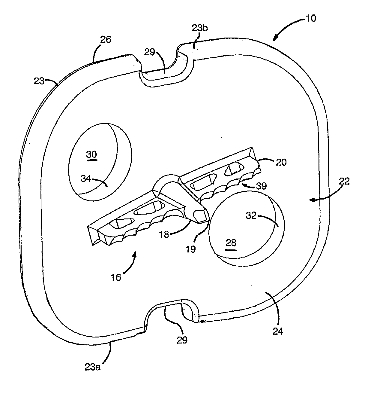
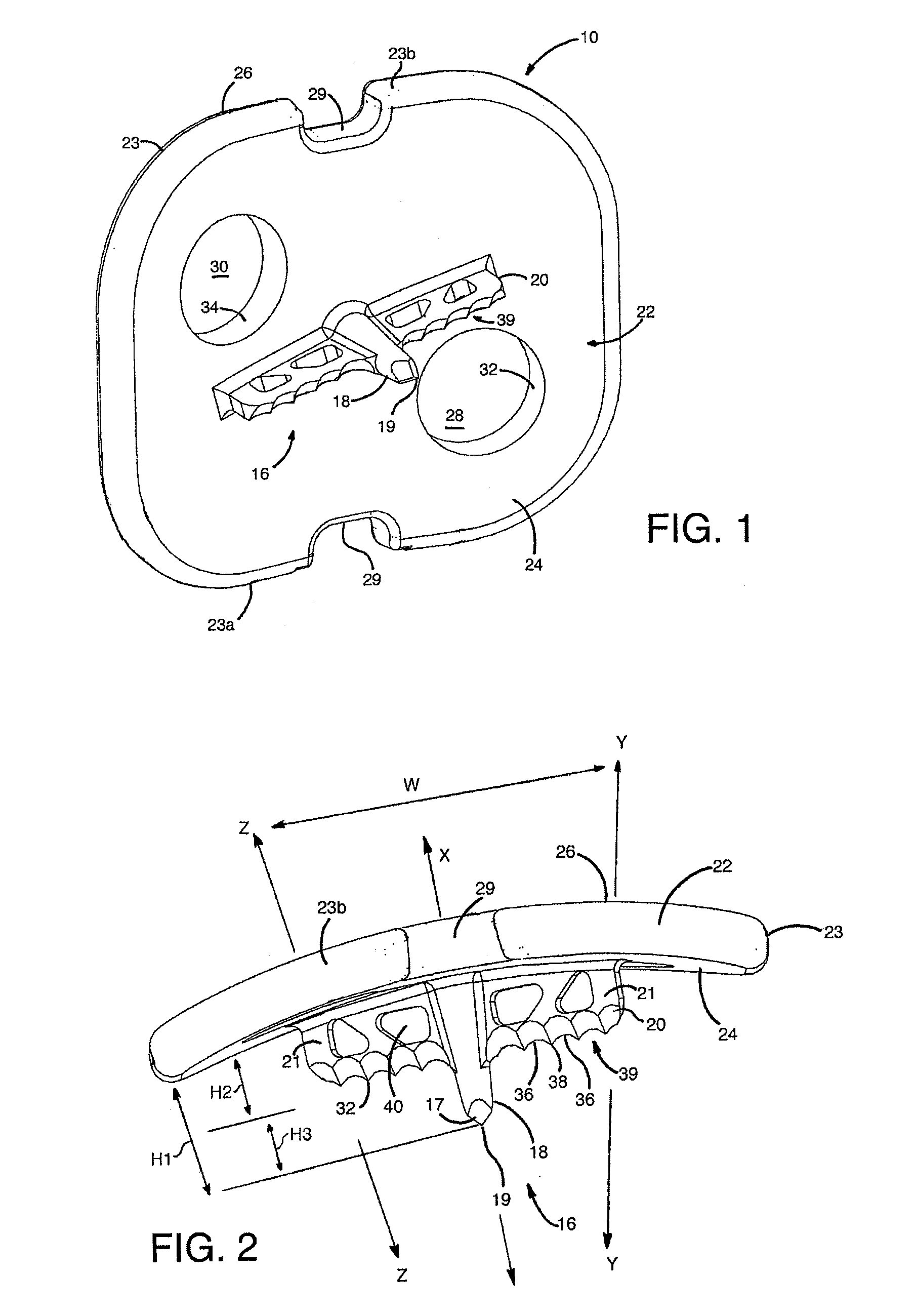
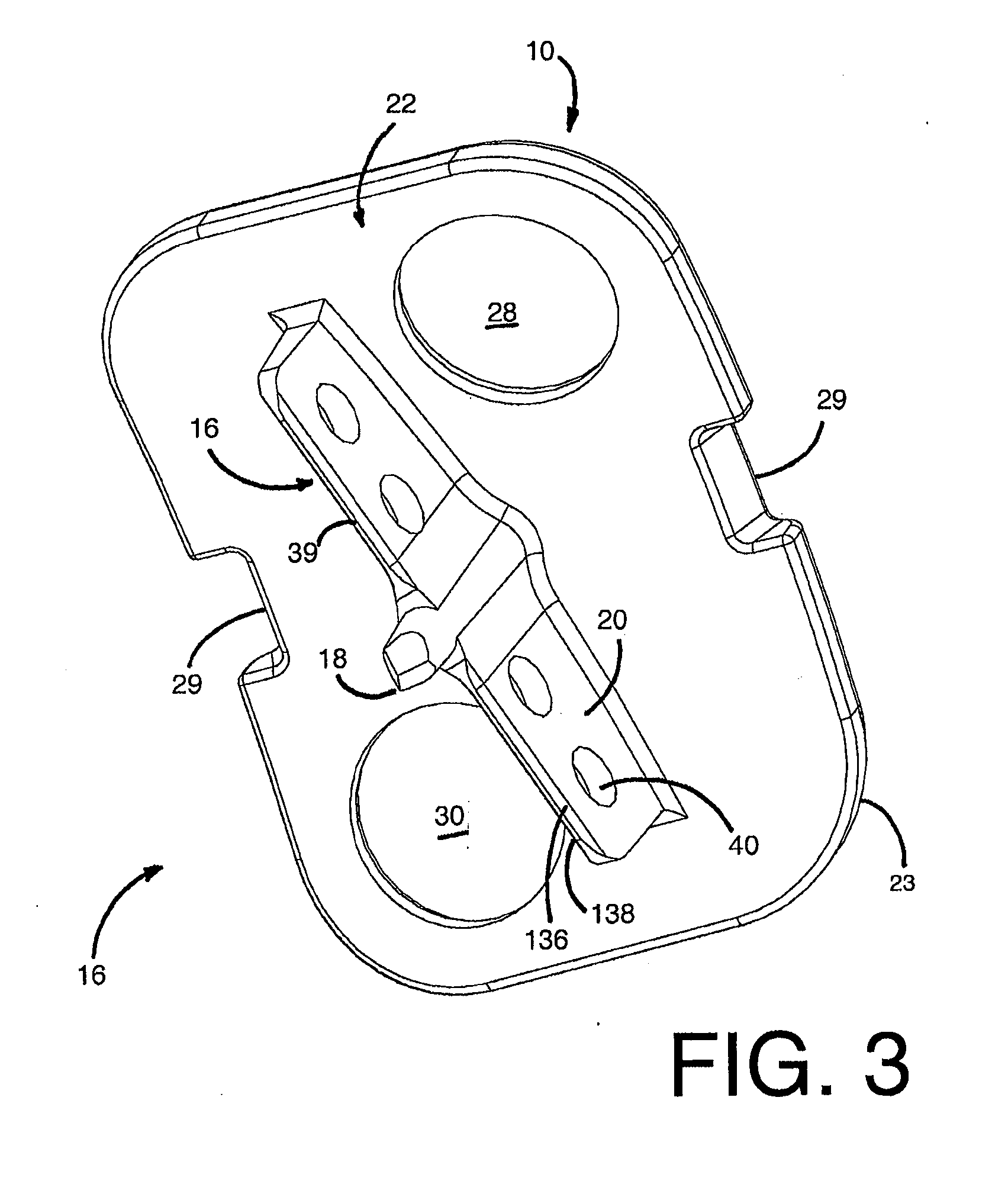
[0039] Referring to FIGS. 1-8, there is illustrated an exemplary mounting device 10 that is arranged and configured for being driven in a bone in order to support at least one, and preferably two, anchor members 12 as part of a stabilizing system 14. Preferably, the mounting device 10 is in the form of a vertebral cleat that is configured for being driven in a vertebral bone as part of a bone stabilization system to fix adjacent vertebrae relative to each other. The mounting device 10 includes a bone securing member 16 with at least one elongate spike portion 18 that permits rotation of the mounting device 10 relative to a bone surface when the spike portion 18 is partially driven into the bone so that a surgeon can orient the mounting device 10 into a final position on the bone. The securing member 16 also preferably includes an elongate keel portion 20 extending transverse to the spike 18 that hinders further rotation of the mounting device 10 when the spike portion 18 and the kee...


PUM


Abstract

A vertebral cleat and a vertebral support system employing the vertebral cleat is provided. Preferably, the vertebral cleat includes a base member having a superior and an inferior surface; an elongate keel portion having a cutting edge thereon depending from the inferior surface of the base member; and a spike portion depending from the inferior surface of the base member, the spike portion having a height that is greater than a height of the elongate keel portion. There is also provided a tool for grasping and implanting the vertebral cleat in a plurality of insertion configurations.

Description

FIELD OF THE INVENTION [0001] The invention relates to bone implants, and in particular, to mounting devices for providing a stable base for bone implant anchor members. BACKGROUND OF THE INVENTION [0002] Bone fixation devices are used in orthopedic surgery to align or fix a predetermined relationship between adjacent bones. One particular use for bone fixation devices is the fixation and alignment of adjacent vertebral bodies. These fixation devices commonly include an elongate rod to set the vertebrae into a desired alignment and various anchoring devices, such as hooks, bolts, wires, screws, and the like that secure the rods to the bone. [0003] A common vertebral fixation device employs a rod and screw system. These systems may include plates that are attached to adjacent vertebrae desired to be fixed in order to provide a mounting base for the fixation device on each vertebrae. A bone screw may then be inserted through openings in each mounting plate and screwed into each adjace...

Claims


Application Information

Patent Timeline
Patent Type & Authority Applications(United States)
IPC IPC(8): A61B17/58A61B17/00A61B17/56
CPCA61B17/7044A61B17/809A61B17/7049
Inventor BERREVOETS, GREGORYNORMAN, MARIAFREDIN, BRAD
Owner PIONEER SURGICAL TECH INC
Why Eureka
Try Eureka