Surgical tool with integral blade and self-centering tip

a surgical tool and self-centering technology, applied in the field of surgical instruments, can solve the problems of inability to accurately place the arthroscope, the risk of clipping a digital nerve, and the limited applicability of arthroscopy for the division of the a1 flexor sheath for trigger fingers, etc., and achieve the effect of simplifying the cross-sectional view

Inactive Publication Date: 2008-05-08
TELLMAN LARS G +1
View PDF34 Cites 44 Cited by
  • Summary
  • Abstract
  • Description
  • Claims
  • Application Information

AI Technical Summary

Problems solved by technology

Such prior art techniques and instruments used to release a retinacular ligament or sheath are not necessarily suited for division of a retinacular sheath such as the A1 pulley that is involved with trigger finger.
Arthroscopy has limited applicability for division of the A1 flexor sheath for trigger finger, due as the very small size of the tendon sheath, and the risk of clipping a digital nerve from inaccurate placement of the arthroscope.
In addition, arthroscopic techniques often require a high degree of surgical expertise and often require relatively bulky, expensive equipment and, accordingly, are not well suited for use in an office environment.
Because of the proximity of the digital nerves on the superficial surface of the flexor sheath, it appears to be possible to wrap a nerve across the advancing tip of the instrument, potentially resulting in a nerve transection with permanent loss of feeling in the finger.
Moreover, unless this technique is used with enough dissection to allow visualization, the surgeon may not be sure that he or she has entered the sheath all the way at one end in order to ensure complete division of the tendon sheath.
Finally, since the tip disclosed is cylindrical in shape, there may be a tendency for the instrument to tend to be displaced to one side of the convex surface of the flexor sheath, risking potential iatrogenic injury to a digital nerve.
However, movement of the flexor tendons may not reliably result in complete division of the sheath from its proximal edge to its distal edge.
In addition, movement of the tendons may cause the pin to simply rotate to accommodate the movement, and may not result in division of the flexor sheath.
Finally, since the sheath is cylindrical in shape being convex dorsally, there may be a tendency for the instrument to be laterally displaced to one side during insertion, which may place the cutting pin outside of the sheath and off to one side.
This instrument is not as applicable in the case of a trigger finger, since the digital nerves run above the flexor sheath and could be at risk for division by the blade.
Moreover, the edge cutting nature of the blade may put the nerves and arteries at risk of being kinked, tied up and divided when advancing this edge cutting knife down the tendon sheath.
Furthermore, there appears to be insufficient room within the Al tendon sheath to allow placement of this instrument.
Also, unlike the transverse carpal ligament which is flat, this risk is heightened in division of the flexor sheath in the finger, since the convex nature of the surface of the sheath would to displace the knife blade off to one side or the other of the sheath.
It is, accordingly, not particularly well suited for application to the A1 pulley of the flexor tendon sheath of the finger, inasmuch as there is insufficient room for placement of this type of jaw, and the required exposure is extensive.

Method used


Image

  • Surgical tool with integral blade and self-centering tip
  • Surgical tool with integral blade and self-centering tip
  • Surgical tool with integral blade and self-centering tip

Examples


Embodiment Construction

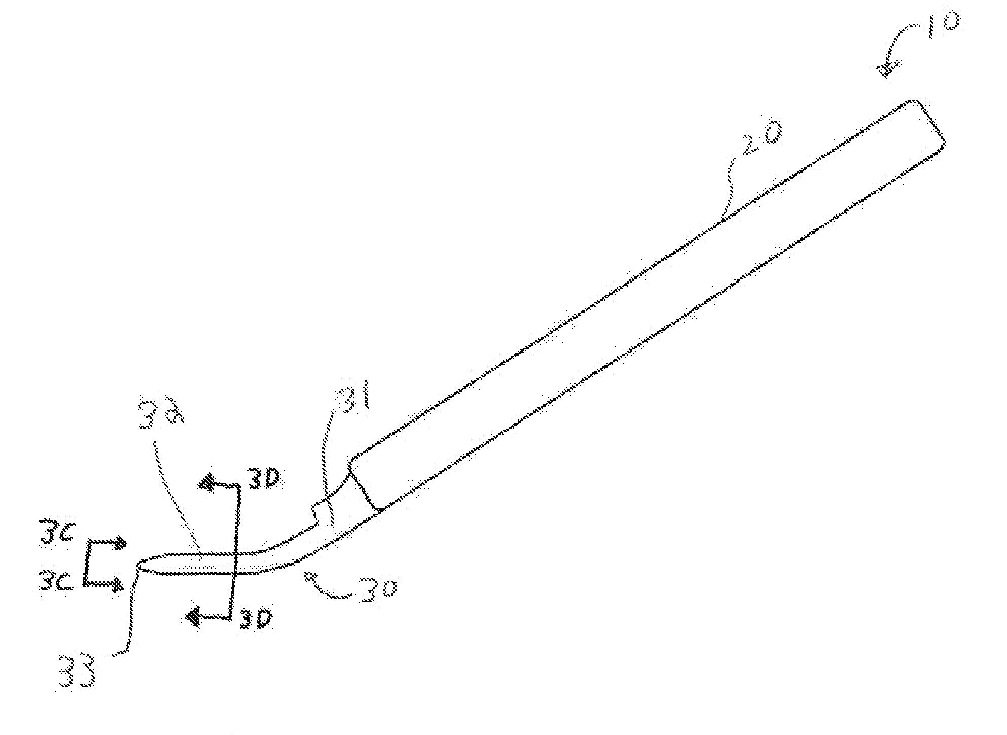
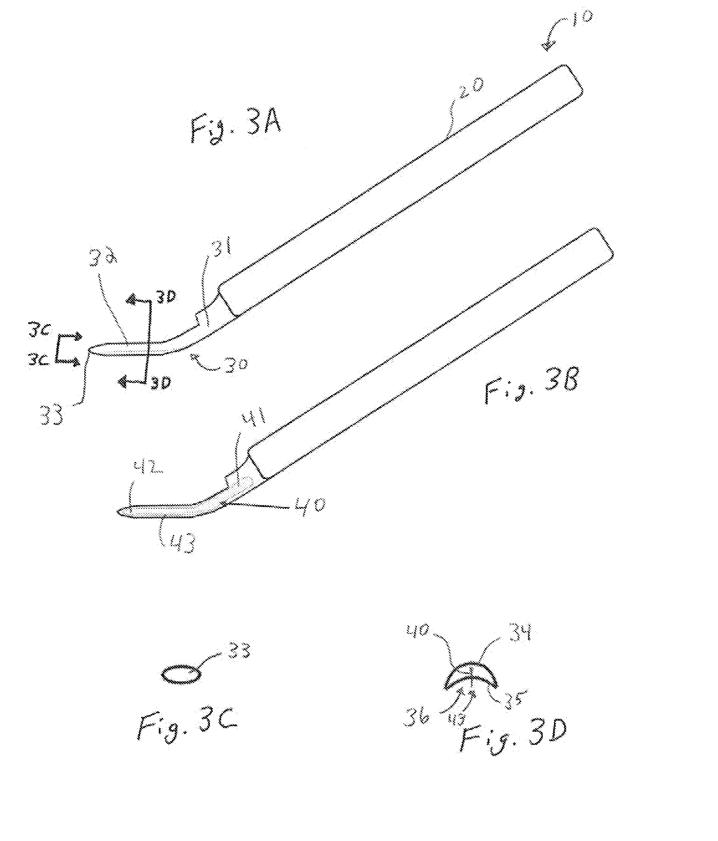
[0062]While several different preferred embodiments are shown in the various FIGS., common reference numerals in the figures denote similar or analogous elements or structure amongst the various embodiments. Moreover, in the figures, the lighter shaded regions indicate structure and / or elements which are hidden from view behind other structure or elements.

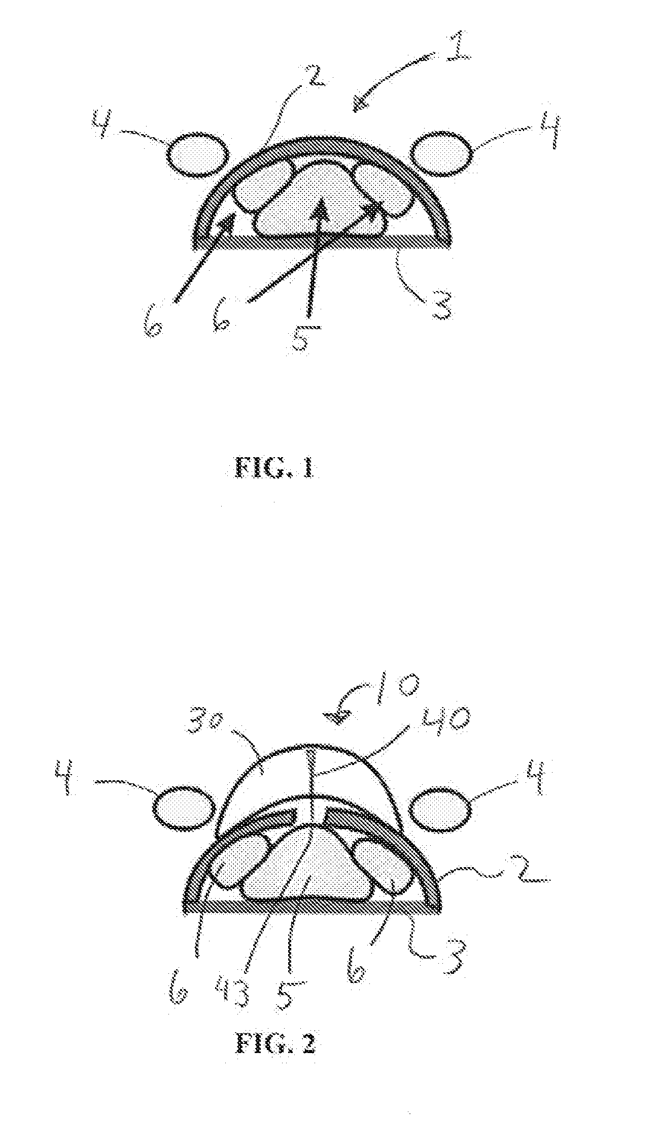
[0063]Referring to FIG. 1, a partial, transverse cross-section of the human hand, proximate the junction of metacarpal and proximal phalanx bones, is shown in simplified form. In particular, the A1 pulley tendon sheath 1 is shown, having a relatively planar floor 3 adjacent metacarpal and proximal phalanx bones (not shown), and an convex, arcuate outer surface 2 extending outwards towards the palm of the hand. The flexor digitorum profundus (FDP) tendon 5 and flexor digitalis superficialis (FDS) tendons 6 are encased within tendon sheath 1 from a region that partially overlies a metacarpal bone extending longitudinally to a region ...


PUM


Abstract

A surgical tool for division of a tendon sheath having a convex outer surface, such as the A1 pulley of the finger, is disclosed. A cutting tip is configured to self-center itself and, in turn, a cutting blade carried by the cutting tip, as the cutting tip is advanced along the arcuate outer surface of the tendon sheath. The cutting tip is further configured to displace neural tissue and vascular tissue from a region proximate the cutting blade as the cutting tip is advanced along the arcuate outer surface of the tendon sheath. A retractable blade guard is disclosed. The cutting blade may be fixed, relative to the cutting tip. Alternatively, the cutting blade may be moveable from a retracted position and a deployed position, and vice-versa.

Description

BACKGROUND OF THE INVENTION[0001]1. Field of the Invention[0002]The invention relates to a surgical instrument to allow division of a tendon sheath in a safe and simplified manner.[0003]Swelling around tendons may lead to pathologic conditions in areas where the tendons traverse a contained space. For instance, the condition of stenosing tenosynovitis in the hand can produce the common condition known as a trigger finger in which an area of irritation or a nodule in the tendon becomes trapped as it passes through the fibrous tunnel known as the A1 pulley in the hand. This may lead to binding of the tendon and interference with movement of the fingers, resulting in the locking and unlocking of the finger as it is flexed that gives the condition its name. Stenosing tenosynovitis of the thumb abductor tendon can cause pain at the wrist and is known as DeQuervain's syndrome; pathologically, it is caused by a similar condition. When swelling occurs within the confines of the carpal tunne...

Claims


Application Information

Patent Timeline
Patent Type & Authority Applications(United States)
IPC IPC(8): A61B17/3209
CPCA61B17/320036A61B2090/08021
Inventor MEDOFF, ROBERT J.
Owner TELLMAN LARS G
Why Eureka
Try Eureka