Thin film energy fabric integration, control and method of making

a technology of energy fabric and thin film, applied in the field of thin film and flexible materials, can solve the problems of inability to store electricity, integrate into a completely flexible system, and no single fabric available to the engineer or designer that has the electrical energy storag

Inactive Publication Date: 2008-05-15
ENERGY INTEGRATION TECH INC
View PDF46 Cites 34 Cited by
  • Summary
  • Abstract
  • Description
  • Claims
  • Application Information

AI Technical Summary

Benefits of technology

[0019] In accordance with another aspect of the present disclosure, the material includes one or more properties of semi-flexibility or flexibility, water resistance or waterproofness, and formed as a thin, sheet-like material or a thin woven fabric.
[0026] In accordance with further aspects of the method, at least one roller is utilized to laminate the layers, the roller having a surface geometry adapted to remove air from between the layers as the lamination process occurs and to not damage the embedded components and the layers. In accordance with another aspect, the layers are adhered together in a manner that forms adhesive battens within the laminate. The layers and the components are, in further embodiments, arranged to be either coplanar or stacked in relationship to one another.

Problems solved by technology

The fabric material itself is not a battery and would be incapable of storing electricity.
With the introduction of organic light emitting polymers (LEPs) and organic light emitting diodes (OLEDs), which are organic polymers, not phosphor films, there is no need for an inverter system, which is problematic to integrate into a completely flexible system.
However, there is currently no single fabric available to the engineer or designer that has the electrical energy storage aspect directly integrated into it and is still thin, flexible, and can be manufactured into a product with the same ease as conventional fabrics.
So far no fabric has emerged with all these characteristics.

Method used


Image

  • Thin film energy fabric integration, control and method of making
  • Thin film energy fabric integration, control and method of making
  • Thin film energy fabric integration, control and method of making

Examples


Embodiment Construction

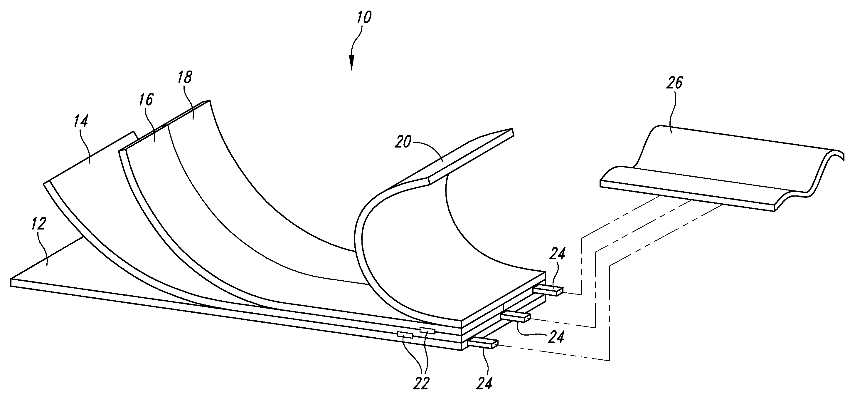
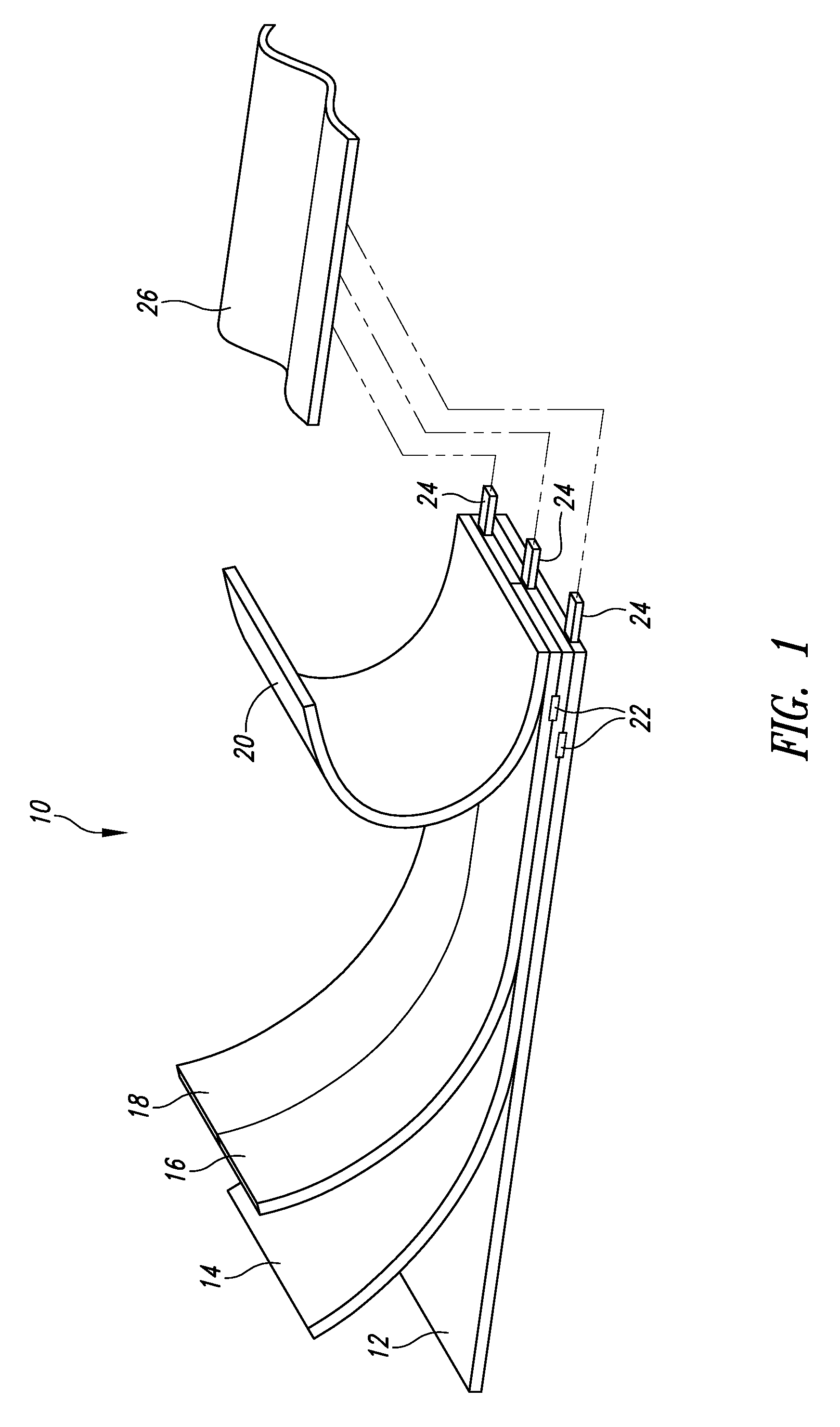
[0042] Referring initially to FIG. 1, shown therein is a flexible sheet 10 formed in accordance with one embodiment of the disclosure.

[0043]FIG. 1 serves to diagrammatically illustrate the flexible sheet form of the finished energy fabric 10 that includes an energy release section 12 and an energy storage section 14. An optional charge section 16 or recharge section 18 or combination thereof is shown along with an optional protective section 20 that can also be a decorative section. These sections can be manufactured separately and then laminated together or each section can be directly deposited on the one beneath it or a combination of both techniques can be employed to produce the final fabric. These sections can be arranged in any order including coplanar arrangements, layers, planes, and other stacking arrangements, and there can be multiple instances of each section in the final fabric.

[0044] The sections can also have different embodiments on the same plane. For instance, a...


PUM

PropertyMeasurementUnit
temperatureaaaaaaaaaa
store energyaaaaaaaaaa

Abstract

A material that includes a first section for storing energy and a second section for collecting and converting energy for storage by the first section in which the stored energy is preferably electrical energy that is used for one from among heat dissipation, heat generation, light emission and powering of an electric circuit in a plurality of devices, ideally covered with a layer to form at least one self-contained panel for operation independently or with other panels to form a system. The material can be formed of layers having devices or components embedded therein, the layers preferably laminated together using a battened pattern of adhesion. A control bus system allows master or slave designation as well as power sharing to the individual panels in the garment as well as among garments.

Description

CROSS-REFERENCE TO RELATED APPLICATION [0001] This application is a continuation-in-part of U.S. patent application Ser. No. 11 / 439,572, filed May 23, 2006, now pending, which application is incorporated herein by reference in its entirety.BACKGROUND OF THE INVENTION [0002] 1. Field of the Invention [0003] The present invention is directed to thin, flexible material and, more particularly, to a flexible fabric having electrical energy storage and release capabilities integrally formed therewith. [0004] 2. Description of the Related Art [0005] There are currently materials that incorporate energy releases in the form of light or heat and are powered by some external, rigid power source. [0006] For example, Coler et al., U.S. Pat. No. 3,023,259, describes a flexible battery that is designed, in one embodiment, to wrap around a person under their clothing so that body heat may be utilized to maintain the electrochemical temperature within a preferred temperature range. The flexible bat...

Claims


Application Information

Patent Timeline
Patent Type & Authority Applications(United States)
IPC IPC(8): A41D31/02B32B5/00B32B37/00
CPCA41D1/002A41D31/0038B32B7/02D03D1/0076Y10T428/24058D03D15/0088D06N3/0002D10B2401/16D10B2501/00D03D15/00A41D31/065D03D15/46
Inventor MORESHEAD, WYLIE
Owner ENERGY INTEGRATION TECH INC
Why Eureka
Try Eureka