Wire Electric Discharge Machining Apparatus And Wire Electric Discharge Machining Method

a technology of electric discharge machining and wire electric discharge, which is applied in the direction of electric circuits, manufacturing tools, instruments, etc., can solve the problems of low productivity, inefficient methods, and easy deterioration of so as to improve productivity and improve straightness accuracy of work

Inactive Publication Date: 2008-05-15
MITSUBISHI ELECTRIC CORP
View PDF3 Cites 46 Cited by
  • Summary
  • Abstract
  • Description
  • Claims
  • Application Information

AI Technical Summary

Benefits of technology

[0025] According to the present invention, it is possible to improve straightness accuracy of a work, prevent electric discharges from being concentrated twice in a row, and, even when a plurality of works made of different materials are stacked, apply optimum machining conditions to the respective materials to simultaneously machine the works. Thus, there is an effect that productivity is improved.

Problems solved by technology

As a result, straightness accuracy of the work is easily deteriorated.
However, considerable time and labor are required for creation of the condition table.
One of causes of breaking of wire in the wire electric discharge machining apparatus is “concentrated discharge” in which electric discharges are concentrated in one place of wire.
This method is inefficient and low in productivity.
However, although it is possible to measure discharge positions between the wire and the work as described above, it is impossible to induce an electric discharge in an arbitrary position.
It is impossible to positively control electric discharges in the discharge positions measured.
It is impossible to perform the shape machining in the Z-axis direction.

Method used


Image

  • Wire Electric Discharge Machining Apparatus And Wire Electric Discharge Machining Method
  • Wire Electric Discharge Machining Apparatus And Wire Electric Discharge Machining Method
  • Wire Electric Discharge Machining Apparatus And Wire Electric Discharge Machining Method

Examples


first embodiment

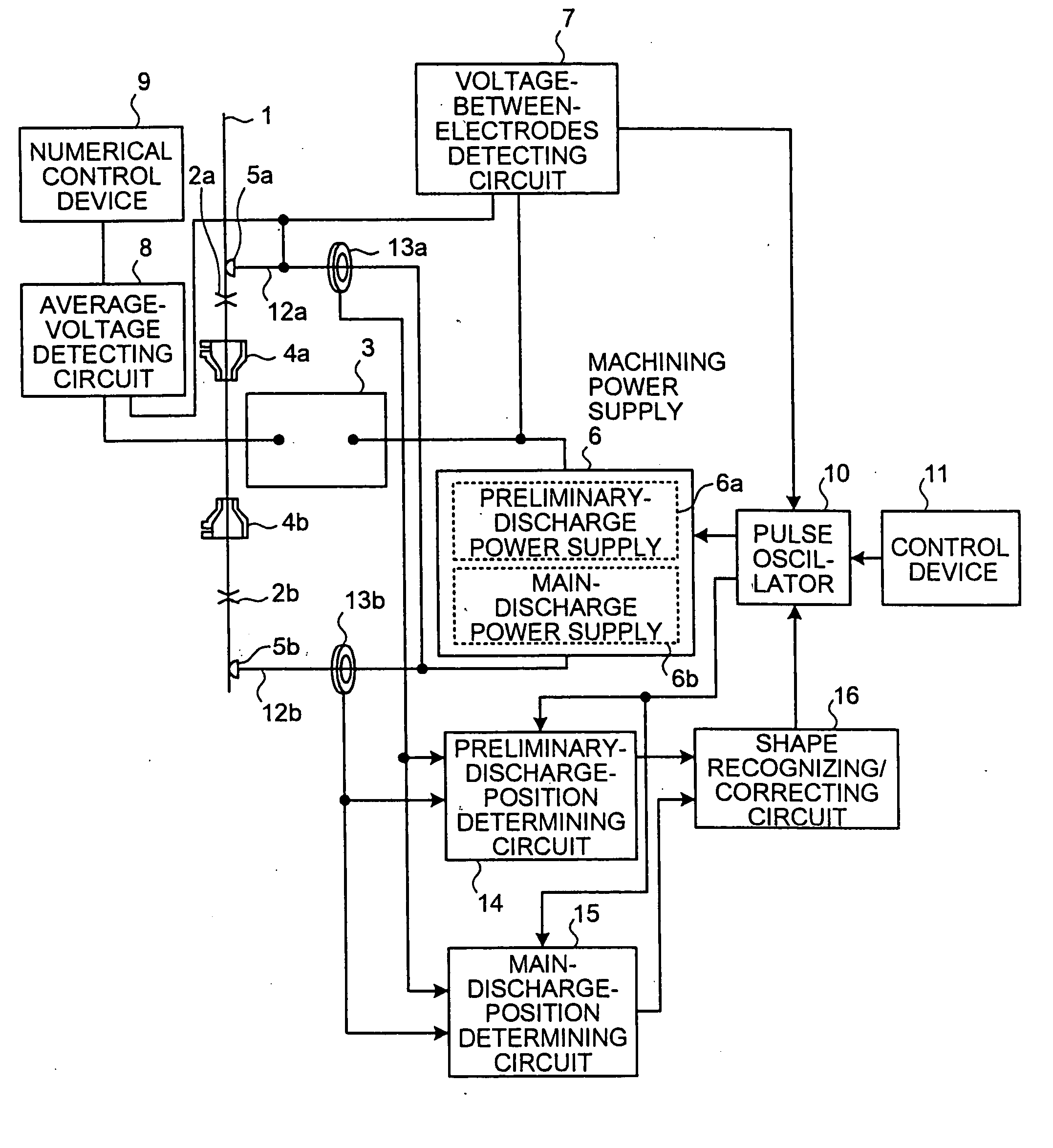
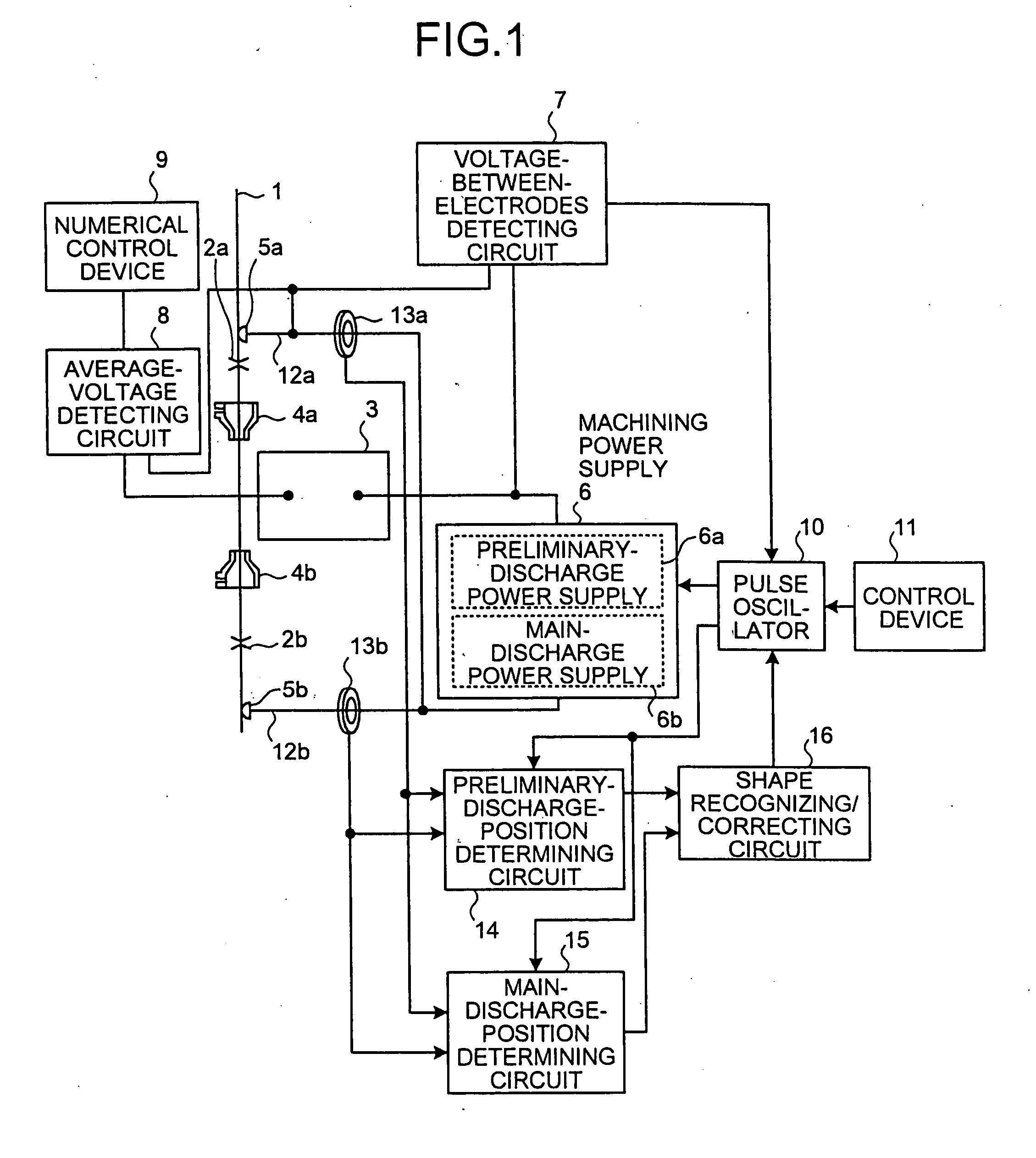
[0074]FIG. 1 is a block diagram of a structure of a wire electric discharge machining apparatus according to a first embodiment of the present invention. In FIG. 1, reference numeral 1 denotes a wire electrode. The wire electrode 1 is guided by wire guides 2a and 2b, which are arranged at an appropriate interval in a vertical direction, to travel, for example, from an upper position to a lower position. In a traveling path of the wire electrode 1 between the wire guides 2a and 2b, a work 3 is arranged to be opposed to the wire electrode 1 at a predetermined interval. Machining fluid nozzles 4a and 4b are provided in positions close to each other in the vertical direction across a position where the wire electrode 1 is opposed to the work 3. High-pressure machining fluid is sprayed from positions above and below the work 3 to the position where the wire electrode 1 and the work 3 are opposed to each other to eliminate discharge machining scrap.

[0075] A feeding point 5a and a feeding...

second embodiment

[0122] In the example a constitution described according to the first embodiment explained above, when it is assumed that an arc voltage is fixed, the machining-energy adjusting unit, which adjusts machining energy that can be calculated as a product of the charge quantity Q set as input power for each electric discharge and the discharge frequency f, adjusts the charge quantity Q, or adjusts a following main discharge current using a preliminary discharge current. In a second embodiment of the present invention, an example of a constitution in adjusting the discharge frequency f is explained with reference to FIG. 5.

[0123]FIG. 5 is a time chart for explaining operations of a wire electric discharge machining apparatus according to the second embodiment of the present invention. S1, S3, Wv, and WI shown in FIG. 5 denote a waveform of a preliminary-discharge voltage pulse, a waveform of a main-discharge voltage pulse, a discharge voltage waveform between the electrodes, and a discha...

third embodiment

[0131] When a relatively long time is required for determining a position and reading out an energy amount after a preliminary discharge current flows, it is likely that generation of a main-discharge voltage-pulse-application stop signal is late for stopping application of a main-discharge voltage pulse and machining is completed without using the main-discharge voltage-pulse-application stop signal generated. In a third embodiment of the present invention, an example of a constitution for coping with this problem is explained. This is an example of a constitution of a mechanism of the discharge-generation control unit.

[0132] In this case, the fact that machining energy is proportional to a charge quantity is utilized. A method of keeping an extremely small electric discharge (which is called “extended discharge”) after preliminary discharge to feed a discharge current (which is called “extended discharge current”) for a predetermined period and, then, switching the preliminary di...


PUM

PropertyMeasurementUnit
peak currentaaaaaaaaaa
discharge currentsaaaaaaaaaa
pause timeaaaaaaaaaa

Abstract

A discharge-generation control unit applies at least a preliminary-discharge voltage pulse and a main-discharge voltage pulse between a wire electrode and a work. A discharge-position determining unit determines a discharge position from results of measurement by a plurality of current measuring units. A machining-energy adjusting unit adjusts machining energy generated by the main-discharge voltage pulse based on a discharge position determined before applying the main-discharge voltage pulse, and reflects a result of the adjustment on the generation of an electric discharge by feeding the result to the discharge-generation control unit.

Description

TECHNICAL FIELD [0001] The present invention relates to a wire electric discharge machining apparatus and a wire electric discharge machining method. BACKGROUND ART [0002] A wire electric discharge machining apparatus is an apparatus that generates a pulse-like electric discharge between a wire serving as an electrode and a work, which are arranged to be opposed to each other in the water, and machines the work into a desired shape using thermal energy of the electric discharge. In the wire electric discharge machining apparatus, the wire is subjected to a reaction force in a direction opposite to a discharge direction after the electric discharge ends. To eliminate discharge machining scrap, in general, high-pressure machining fluid is spayed from positions above and below a position where the wire is opposed to the work to the opposed position. The wire is vibrated by the discharge reaction force, the spray of the machining fluid, and the like. As a result, straightness accuracy o...

Claims


Application Information

Patent Timeline
Patent Type & Authority Applications(United States)
IPC IPC(8): B23H1/00
CPCB23H7/04B23H1/022
Inventor HASHIMOTO, TAKASHISATOU, TATSUSHIIWATA, AKIHIKOUKAI, YOSHIKAZUONODERA, YASUO
Owner MITSUBISHI ELECTRIC CORP
Why Eureka
Try Eureka