

Projector
a projector and projector technology, applied in the field of projectors, can solve the problems of projectors not being properly oriented, projectors may not be easy to use by users, and light from the light source can accidentally enter the eyes of people around the projector device, so as to reduce the amount of light emitted
- Summary
- Abstract
- Description
- Claims
- Application Information
AI Technical Summary
Benefits of technology
Problems solved by technology
Method used
Image

Examples
first embodiment
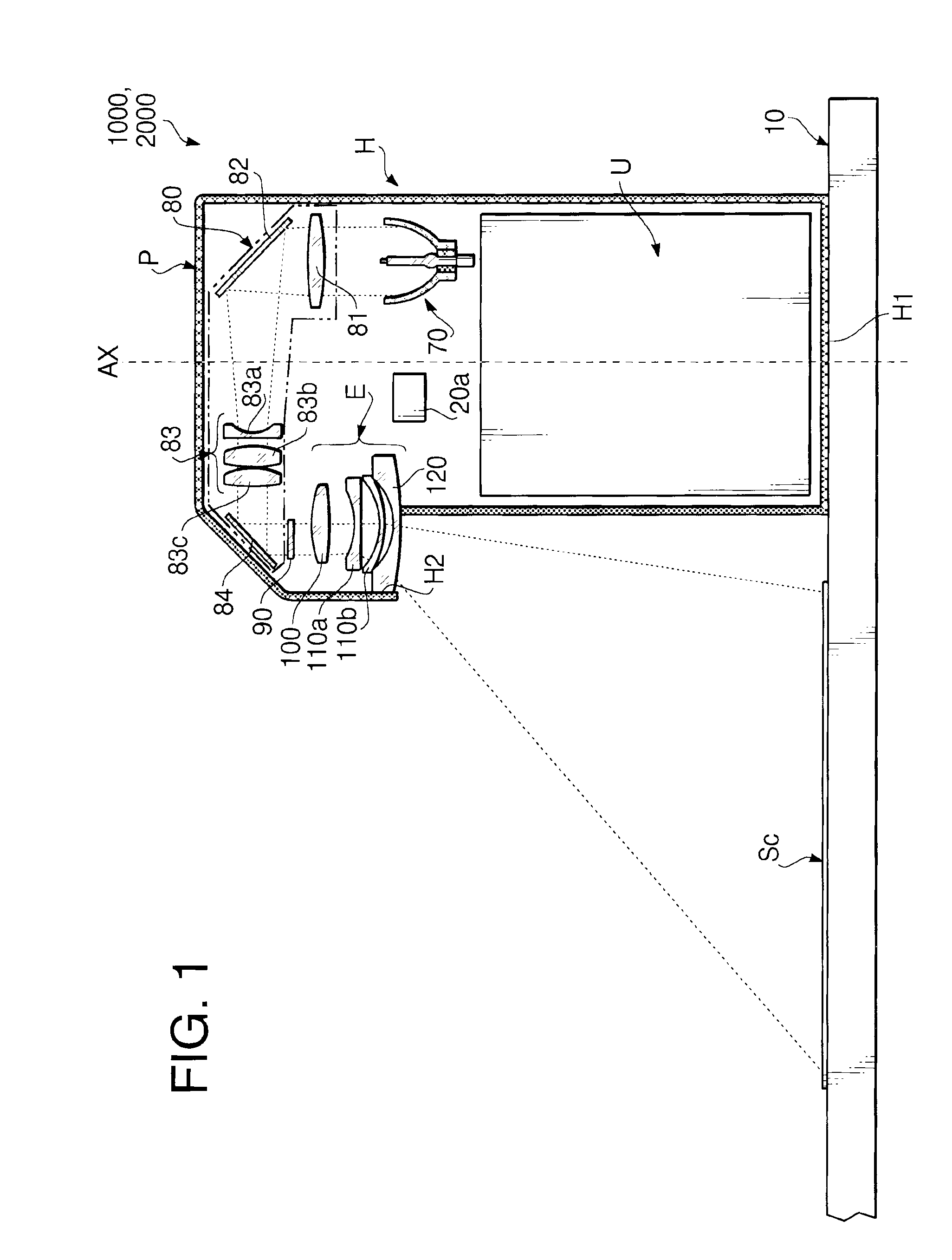
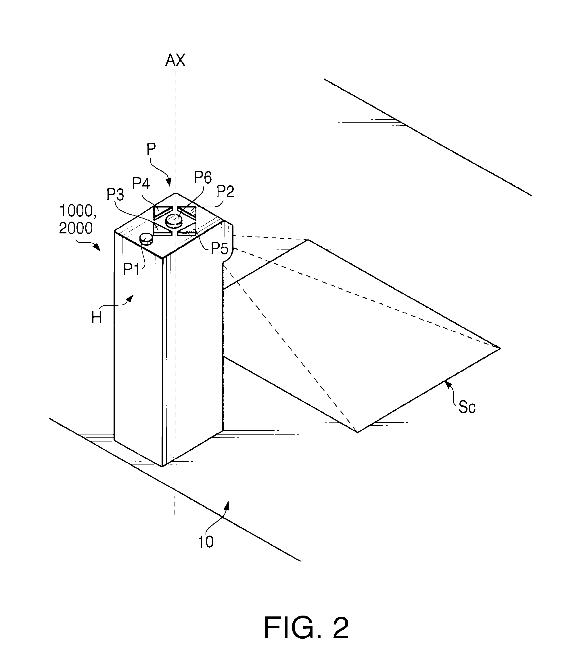
[0068]FIG. 1 is a schematic cross-sectional view showing a projector 1000 according to a first embodiment of the present invention. FIG. 2 is a perspective view showing the projector 1000 being placed on a table 10 according to the first embodiment of the present invention. The projector 1000 is a desktop type and has a housing H, which is placed on a table 10 on its bottom H1.
[0069]As shown in FIGS. 1 and 2, the projector 1000 includes an operation panel P, a control unit U, a lamp 70, an illuminating optical system 80, a transmissive liquid crystal panel (hereinafter referred to as LCD) 90, and an imaging optical system E.
[0070]The operation panel P, which is arranged on an upper surface of the housing H, includes a plurality of push keys. The push keys include an operation menu display key P1, an up key P2, a down key P3, a left key P4, a right key P5, and an enter key P6.
[0071]The operation menu display key P1 is pressed by a user for projecting a subsidiary image for an operati...
second embodiment
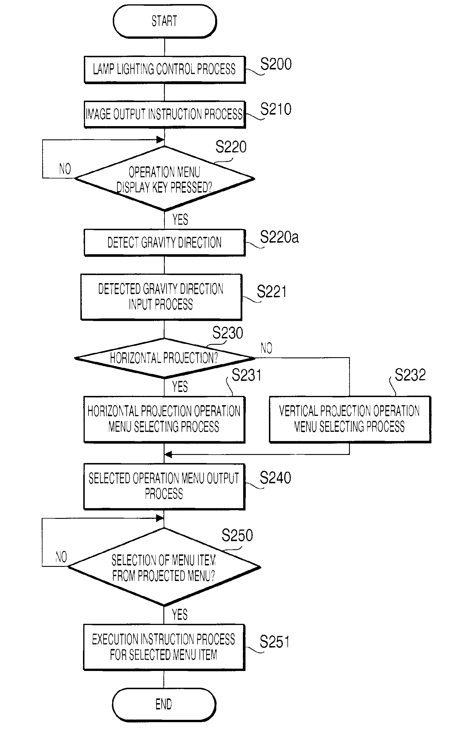
[0136]FIG. 11 shows a first part of a flowchart showing an operation of the microcomputer 20 of the projector 2000 according to the second embodiment of the present invention. FIG. 12 shows a second part of the flowchart showing the operation of the microcomputer 20 of the projector 2000 according to the second embodiment of the present invention. FIGS. 13A-13C illustrate a common menu, a horizontal projection operation menu, and a vertical projection operation menu stored in a ROM of the microcomputer 20 of the projector 2000 according to the second embodiment of the present invention. In the present and the following embodiments, a configuration similar to that of the first embodiment is referred to by an identical reference numeral, and description of that will be omitted. It is noted in the second embodiment that operation shown in FIG. 4 in the first embodiment is replaced with the operations shown in FIGS. 11, 12.
[0137]In the second embodiment, a common menu key (not shown) an...
third embodiment
[0175]FIG. 14 is a perspective view of an image projected on a vertically oriented board 3010 and a projector 3000 supported on an upper edge part of the board according to a third embodiment of the present invention. FIG. 15 is a cross-sectional view of the projector 3000 taken along the line XV-XV in FIG. 14 according to the third embodiment of the present invention. A configuration of a circuit of the projector 3000 according to the third embodiment of the present invention is similar to that of projector 1000, which is shown in FIG. 3. The projector 3000 has a housing H, which horizontally extends from an upper edge part of the board 3010 toward the front of the board 3010 as shown in FIG. 14. Incidentally, the board 3010 is supported by a frame (not shown) to be oriented in an upright position.
[0176]The housing H includes a housing body Ha and a fixing member Hb. The housing body Ha is fixed onto the surface of the upper edge part of the board 3010, with its bottom H1 contactin...
PUM
 Abstract
Description
Claims
Application Information