
Arc suppression circuit using a semi-conductor switch

a semi-conductor switch and circuit technology, applied in the direction of circuit-breaking switches, circuit-breaking switches for excess current, circuit-breaking switch details, etc., can solve the problems of well-known problems such as undesirable arcing

Inactive Publication Date: 2008-05-15
ABB TECH AG
View PDF6 Cites 30 Cited by
  • Summary
  • Abstract
  • Description
  • Claims
  • Application Information

AI Technical Summary

Benefits of technology

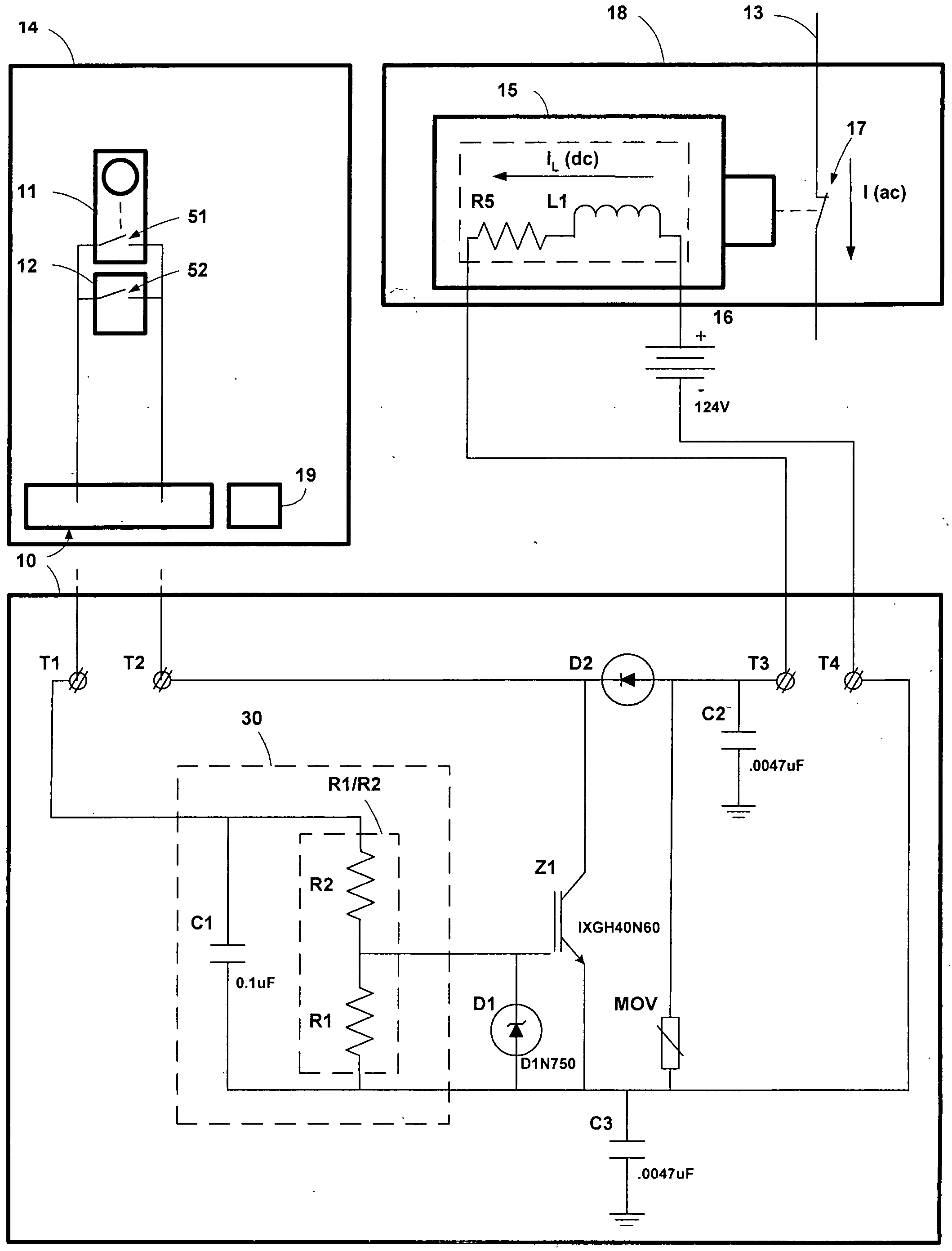
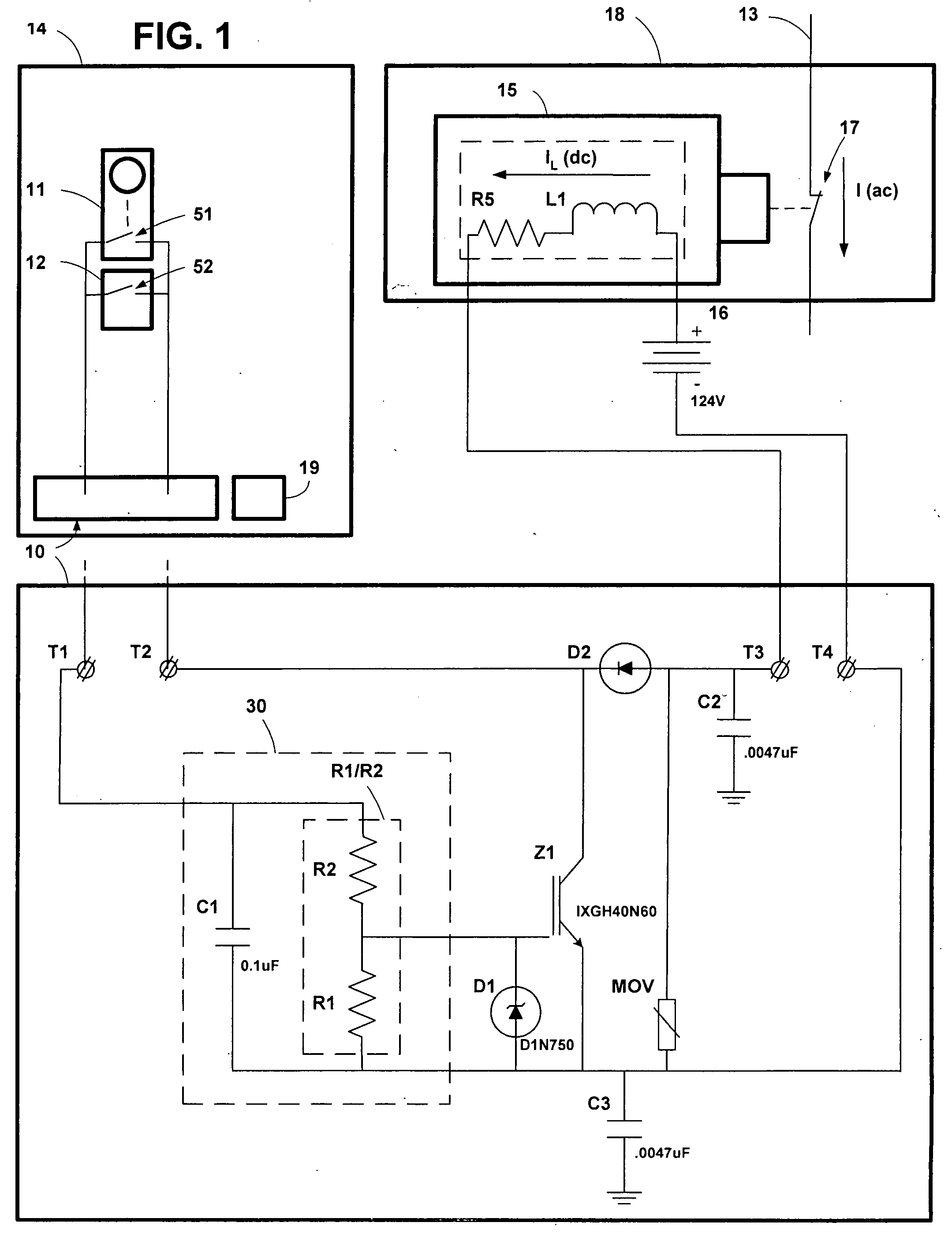
[0007]In a first preferred embodiment, the arc suppression circuit includes trip contacts that are coupled to operate a battery-powered solenoid. The semi-conductor switch is an insulated gate bipolar junction transistor (IGBT) connected across the battery-powered solenoid of an AC power circuit breaker and coupled to a switch-control circuit for turning on and turning off the semi-conductor switch.
[0008]The switch-control circuit is configured such that the semi-conductor switch is already on, providing a current path around the contacts, when the contacts begin to open, and such that the semi-conductor switch remains on and continues to provide a current path around the contacts for a sufficient time after the contacts begin to open to prevent an arc from becoming established
[0009]In a first preferred embodiment, the semi-conductor switch is an insulated gate bi

Problems solved by technology

Arcing is a well known problem in AC power switching.
Arcing is well known to be undesirable because of the wear that arcing inflicts on the contacts, and because of undesirable circuit effects caused by arcing.

Method used


Image

  • Arc suppression circuit using a semi-conductor switch
  • Arc suppression circuit using a semi-conductor switch
  • Arc suppression circuit using a semi-conductor switch

Examples


second embodiment

2) Second Embodiment of the Invention

[0051]FIG. 5 is a circuit diagram showing a second embodiment of the arc suppression circuit of the present invention.

[0052]In this second embodiment, the arc suppression circuit provides a semi-conductor switch configured to accept control signals from a microprocessor within the protection relay. The microprocessor controls the timing of the switching on of the semi-conductor switch. The microprocessor turns the switch on before the contacts begin to open, thereby providing a current path around the contacts before the contacts begin to open. The semi-conductor switch is turned off after a predetermined time, a time sufficient to prevent an arc from becoming established. In a preferred mode, the predefined time is determined by the microprocessor. In an alternative mode, the predefined time is determined by the time constant of a resistance and the parasitic capacitance of the semi-conductor switch.

[0053]Referring to FIG. 5, arc suppression cir...


PUM


Abstract

An arc suppression circuit in a protection relay having trip contacts is used to turn off a battery-powered solenoid and trip an AC power circuit breaker. The arc suppression circuit uses a switch-control circuit to control the turning off of a semi-conductor switch so that the semi-conductor switch provides a current path around the trip contacts, and is carrying all, or substantially all, of the load current, before the trip contacts are opened. When the trip contacts begin to open, the switch-control circuit holds the semi-conductor switch on for a sufficient time to prevent an arc from becoming established before turning the semi-conductor switch off. In a second embodiment, the arc suppression circuit provides a second switch-control circuit. This second switch-control circuit is configured to accept control signals from a microprocessor within a protection relay. The microprocessor turns the semi-conductor switch on before the contacts begin to open, thereby providing a current path around the contacts before the contacts begin to open. The microprocessor turns the semi-conductor switch off after a time sufficient to prevent an arc from becoming established.

Description

TECHNICAL FIELD[0001]This invention relates generally to circuits in AC power distribution switching systems used to control AC power circuit breakers. More specifically the invention relates to arc suppression circuits for protecting trip contacts that may be used to switch off an inductive DC current load such as the inductive load presented by the “opening solenoid” associated with an AC power circuit breaker.BACKGROUND[0002]Arcing is a well known problem in AC power switching. Arcing is the creation of an electrical arc between the contacts as they begin to open from a closed position. If, as the contacts open, the voltage across the contacts reaches a sufficient level, an arc will form between the contacts. Furthermore, if an arc does form, the arc may continue even after the contacts are well open. Arcing is well known to be undesirable because of the wear that arcing inflicts on the contacts, and because of undesirable circuit effects caused by arcing.[0003]Protection relays ...

Claims


Application Information

Patent Timeline
IPC IPC(8): H01H9/54
CPCH01H9/542H01H2009/546H01H2009/544H01H2009/543
Inventor MAHARSI, MOHAMEDVODA, DOUGLAS A.GLACOBBE, MARK C.SAYOUMI, DELA SALAH-ELDINWOOD, DOUGLAS A.
Owner ABB TECH AG
Learn More