Switch chassis

a switch chassis and switch technology, applied in the direction of printed circuit aspects, orthogonal pcbs mounting, electrical apparatus construction details, etc., can solve the problems of several constraints, achieve the effect of improving internal signal integrity, simplifying the design of printed circuit boards, and improving electrical signal characteristics

Inactive Publication Date: 2008-05-15
SUN MICROSYSTEMS INC
View PDF14 Cites 104 Cited by
  • Summary
  • Abstract
  • Description
  • Claims
  • Application Information

AI Technical Summary

Benefits of technology

[0018]Passing the signals through the pass-though vias can simplify the design of a printed circuit board forming the plane and can provide improved electrical signal characteristics compared to prior approaches. In one example up to a total of 55,296 circuits can cross the printed circuit board. In an example embodiment a 110 Terabits per second (Tbps) printed circuit board

Problems solved by technology

There are, however, several constrain

Method used


Image

  • Switch chassis
  • Switch chassis
  • Switch chassis

Examples


Embodiment Construction

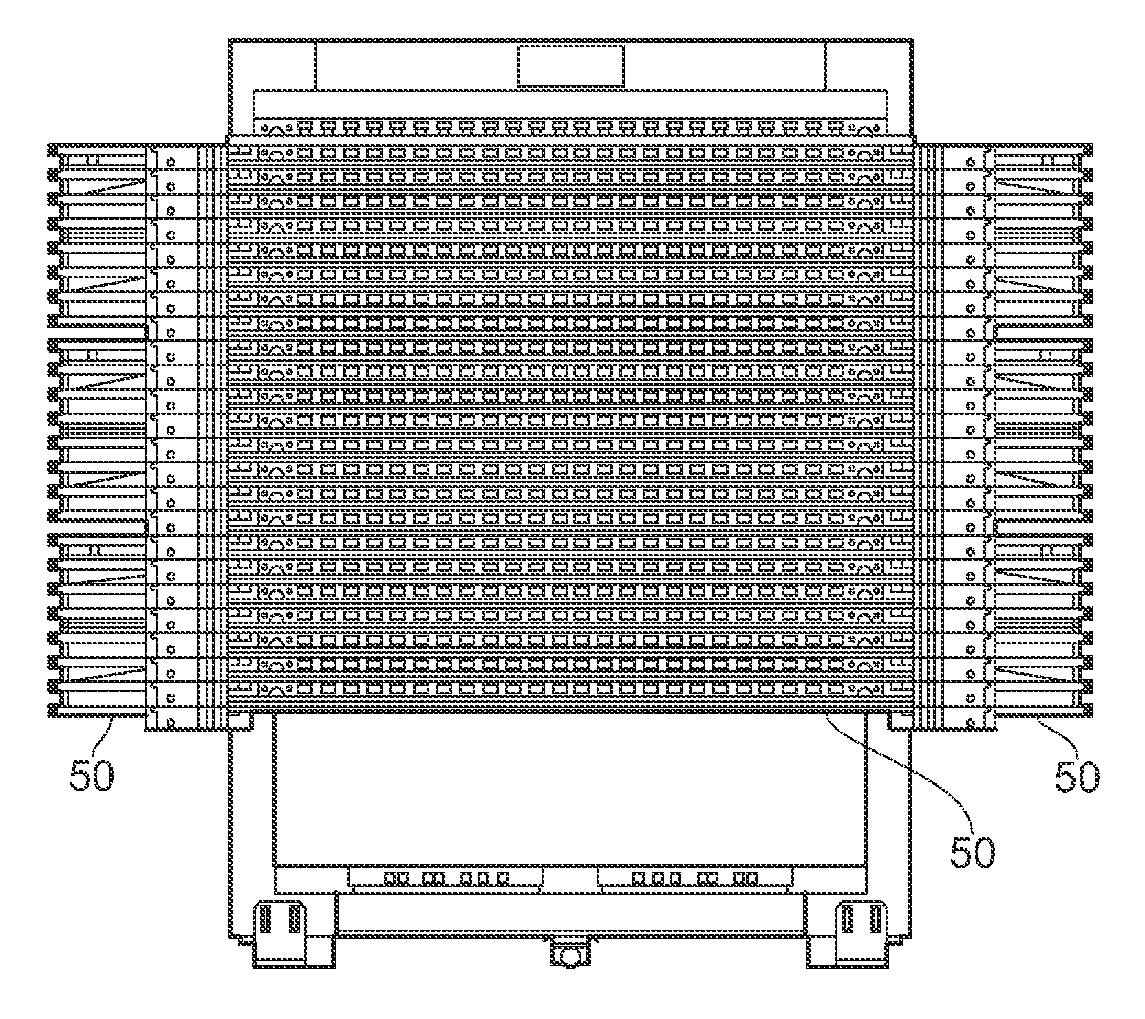
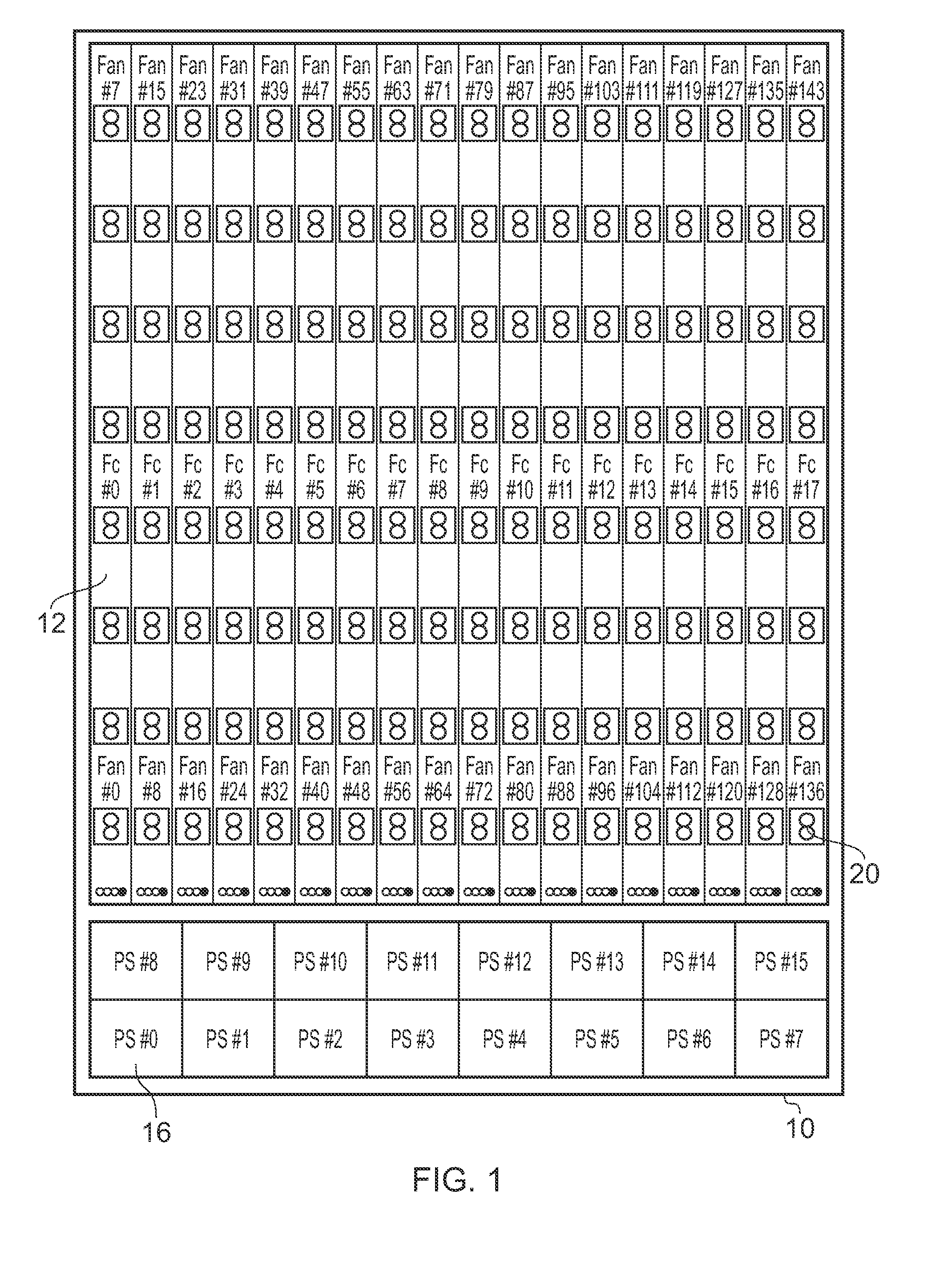
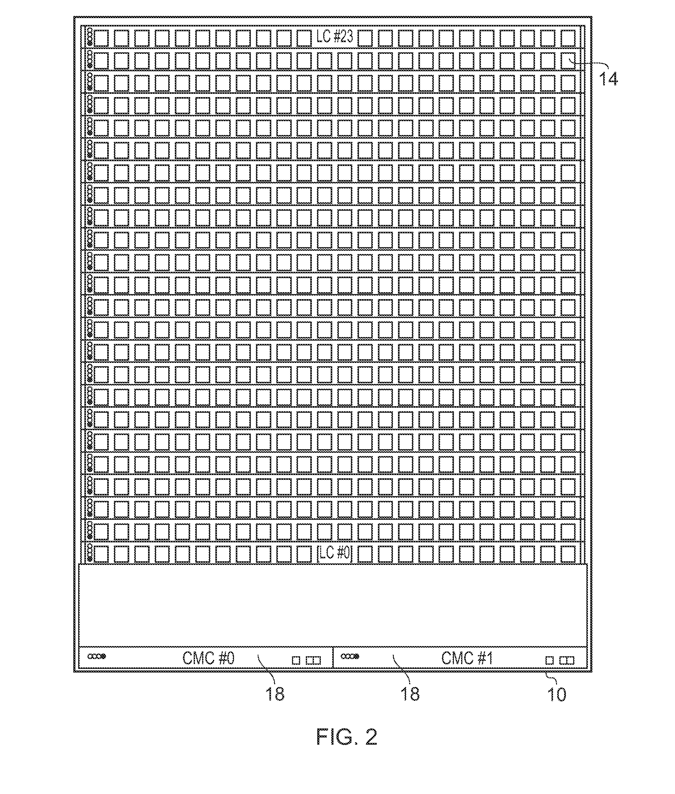
[0048]An example embodiment of the invention will be described that provides a 3456-port Infiniband 4× DDR switch in a custom rack chassis, with the switch architecture being based upon a 5-stage CLOS fabric. The rack chassis can form a switch enclosure.

[0049]The CLOS network, first described by Charles Clos in 1954, is a multi-stage fabric built from smaller individual switch elements that provides full-bisectional bandwidth for all end points, assuming effective dispersive routing.

[0050]Given that an external connection (copper or fiber) costs several times more per port than the silicon cost, to make large CLOS networks practical an aim is to minimize the number of external cables required and to maximize the number of internal interconnections. This reduces the cost and increases the reliability. For example, a 5-stage fabric constructed with switching elements of size (n) ports supports (n*n / 2*n / 2) edge points, using (5*n / 2*n / 2) switch elements with a total of (3*n*n / 2*n / 2) con...


PUM


Abstract

A switch chassis includes a plane having pass-through vias. An array of connector pairs is provided. A connector pair includes a first multi-path connector on first side of the plane and a second multi-path connector on the second side of the plane interconnected through the pass-through vias in the plane. Fabric cards can be connected to respective columns of first connectors and line cards can be connected respective rows of second connectors of the connector pairs to orient the fabric and lines cards orthogonally with respect to each other.

Description

RELATED APPLICATION[0001]This application hereby claims priority under 35 U.S.C. §119 to U.S. Provisional Patent Application No. 60 / 858,180 filed 10 Nov. 2006, entitled “Switch Chassis,” by inventors Ola Torudbakken, Andreas Bechtolsheim, Gilbert Figueroa, Hon Hung Yam.BACKGROUND[0002]The invention relates to communications switch systems.[0003]When constructing a large switch fabric with, for example, a Clos based fabric topology, it is desirable to minimize various parameters such as the number of cables, the number of individual switch chassis instances involved and the number of switch stages. The reasons for this include reducing the volume of the switch fabric, reducing latency, and increasing reliability.[0004]For those reasons, it is desirable to have a single large switch chassis with high enough radix (number of ports) to enable connectivity to all relevant end-nodes in the set of possible target cluster configurations. There are, however, several constraints when building...

Claims


Application Information

Patent Timeline
IPC IPC(8): H05K7/04H05K7/20
CPCH04Q1/04H04Q1/08H05K1/14H05K7/1445H04Q1/03H05K2201/10189H05K2203/1572H04Q1/035H04Q1/06H05K2201/044
Inventor TORUDBAKKEN, OLABECHTOLSHEIM, ANDREASFIGUERA, GILBERTOYAM, HON HUNG
Owner SUN MICROSYSTEMS INC
Why Eureka
Try Eureka