Assembly element including two series of elastic structures and timepiece fitted with the same
a technology of elastic structure and assembly element, which is applied in the field of assembly element and timepiece, can solve the problem of not being able to drive a hollow cylinder onto a conventional rotating arbour, and achieve the effect of optimizing the resistance to linear acceleration
- Summary
- Abstract
- Description
- Claims
- Application Information
AI Technical Summary
Benefits of technology
Problems solved by technology
Method used
Image
Examples
first embodiment
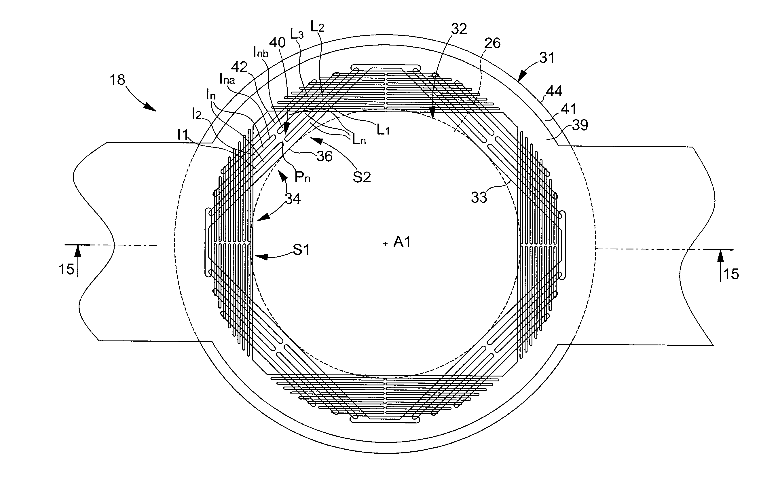
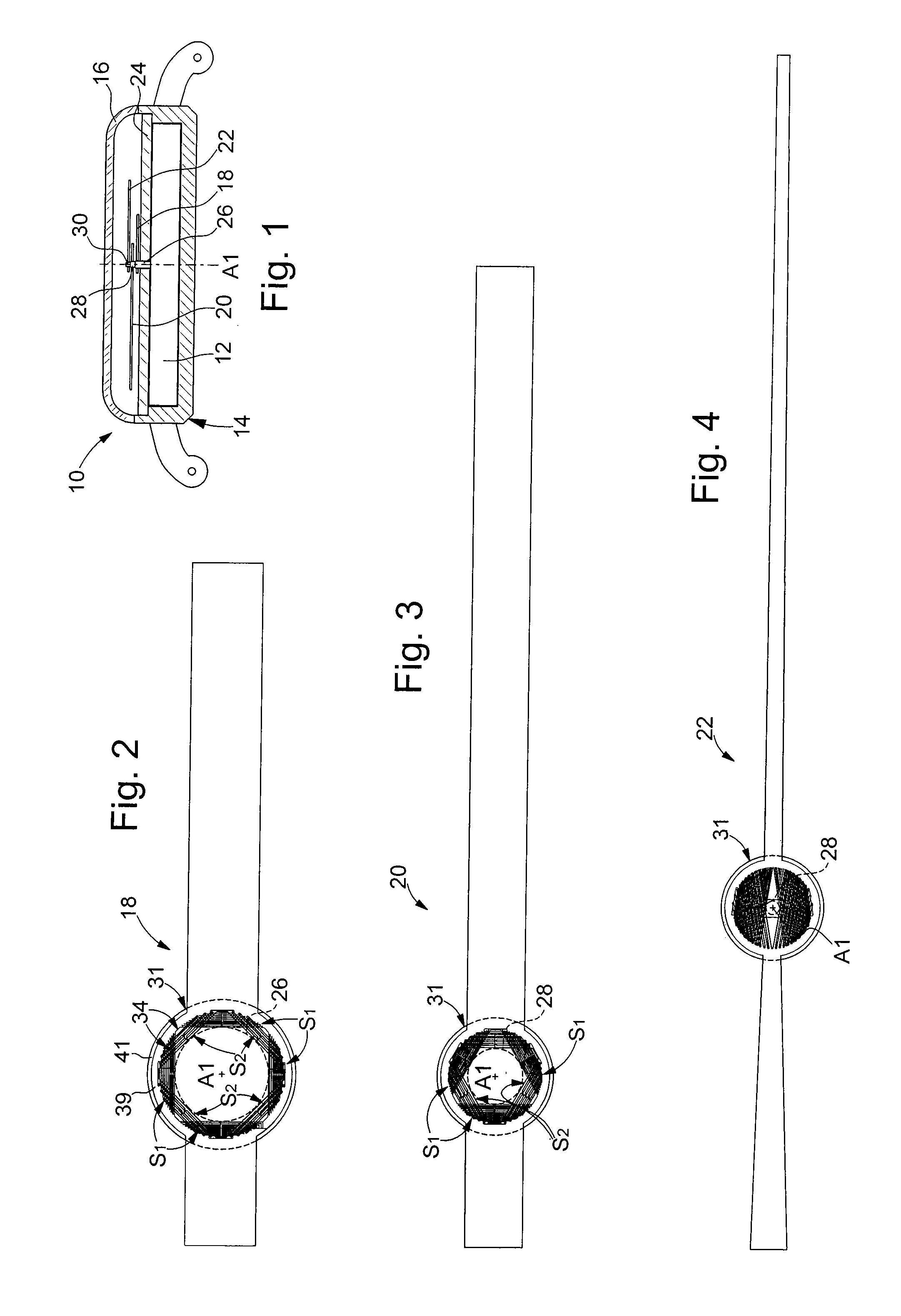
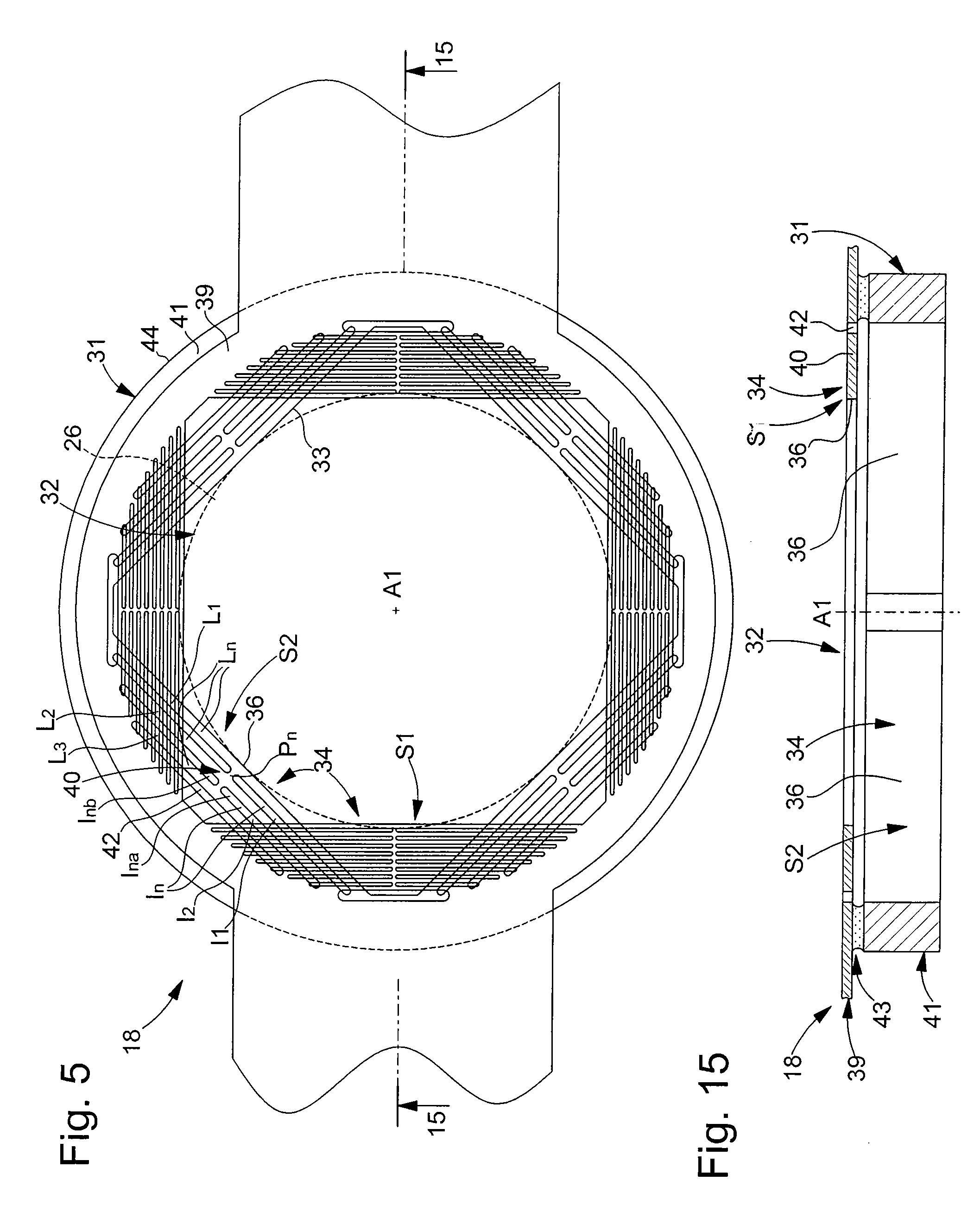
[0042] the elastic structures 34 of the first series S1 and second series S2 are of similar types, here of the type comprising a radial stack of rectilinear and parallel strips Ln of substantially constant radial thickness. Elastic strips Ln each extend along a tangential direction relative to the associated arbour 26. The support surface 36 of each elastic structure 34 is arranged on the inner face 38 of the first elastic strip L1 of the stack, on the side of arbour 26. In each elastic structure 34, each elastic strip Ln is separated radially from the adjacent elastic strip Ln+1, Ln−1 by a rectilinear separator hole In in two parts Ina, Inb, the two parts Ina, Inb of separator hole In being separated by a bridge of material Pn which connects the two adjacent elastic strips Ln and which is substantially aligned radially with support surface 36. The continuous series of bridges of material Pn between elastic strips Ln thus forms a radial connecting beam 40.
[0043]Advantageously, the e...
second embodiment
[0071] the two branches 58, 60 of each elastic structure 34 are bent towards each other forming an almost closed “C”.
[0072]This second embodiment is described considering the hour hand 18 as shown in FIG. 9. It will be noted that the elastic structure, 34 are here represented at rest i.e. before being deformed by the insertion of the associated arbour 26, 28, 30.
[0073]Each branch 58, 60 of each elastic structure 34 has the shape of a substantially parabolic curve, a first fixed end 70, 72 of which is arranged on the associated bridge of material 56 and a second free end 66, 468 of which faces the free end 66, 68 of the other branch 58, 60 of elastic structure 34.
[0074]Preferably the free ends 66, 68 of branches 58, 60 of each elastic structure 34 are sufficiently close that the inner face of each branch 58, 60 is substantially tangent to the axial surface of arbour 26, in proximity to the free ends 46, 68, the support surface 6264 of each branch 58, 60 thus being located on the inne...
third embodiment
[0079]The third embodiment has the advantage of producing a self-locking effect, when arbour 26, 28, 30 and the associated hand 18, 20, 22 are assembled to each other. Indeed, the inclination of branches 58, 60 allows a dynamic reaction to an acceleration in rotation which makes this embodiment particularly suited to securing assembly elements subject to high angular accelerations or in the event that the rotating element has a significant unbalance in the distribution of weights, which is the case for the hands of a timepiece.
[0080]In the third embodiment, the two branches 58, 60 of each elastic structure 34 exert thrust efforts in opposite directions, such that each branch 58, 60 opposes the relative rotation of hand 18, 20, 22 relative to the associated arbour 26, 28, 30 in a preferred direction of rotation. In the example shown in FIG. 12, the first branch 58 of each elastic structure 34 opposes the relative rotation of hand 18 in the anticlockwise direction and the second branc...
PUM
 Abstract
Description
Claims
Application Information
 - R&D
- Intellectual Property
- Life Sciences
- Materials
- Tech Scout
- Unparalleled Data Quality
- Higher Quality Content
- 60% Fewer Hallucinations
Browse by: Latest US Patents, China's latest patents, Technical Efficacy Thesaurus, Application Domain, Technology Topic, Popular Technical Reports.
© 2025 PatSnap. All rights reserved.Legal|Privacy policy|Modern Slavery Act Transparency Statement|Sitemap|About US| Contact US: help@patsnap.com


