Shield assembly apparatus for an x-ray device

a shield assembly and shield technology, applied in x-ray tubes, nuclear engineering, nuclear elements, etc., can solve the problems of high g-loading, difficult to meet the requirements of x-ray devices, and high cos

Inactive Publication Date: 2008-05-15
GENERAL ELECTRIC CO
View PDF15 Cites 16 Cited by
  • Summary
  • Abstract
  • Description
  • Claims
  • Application Information

AI Technical Summary

Problems solved by technology

Conventional lead shields are located in a housing that surrounds the entire x-ray tube assembly containing a substantial amount of lead and are consequently very heavy as the size of the x-ray tube increases.
T...

Method used


Image

  • Shield assembly apparatus for an x-ray device
  • Shield assembly apparatus for an x-ray device
  • Shield assembly apparatus for an x-ray device

Examples


Embodiment Construction

[0014]In the following detailed description, reference is made to the accompanying drawings that form a part hereof, and in which is shown by way of illustration specific embodiments that may be practiced. These embodiments are described in sufficient detail to enable those skilled in the art to practice the embodiments, and it is to be understood that other embodiments may be utilized and that logical, mechanical, electrical and other changes may be made without departing from the scope of the embodiments. The following detailed description is, therefore, not to be taken as limiting the scope of the invention.

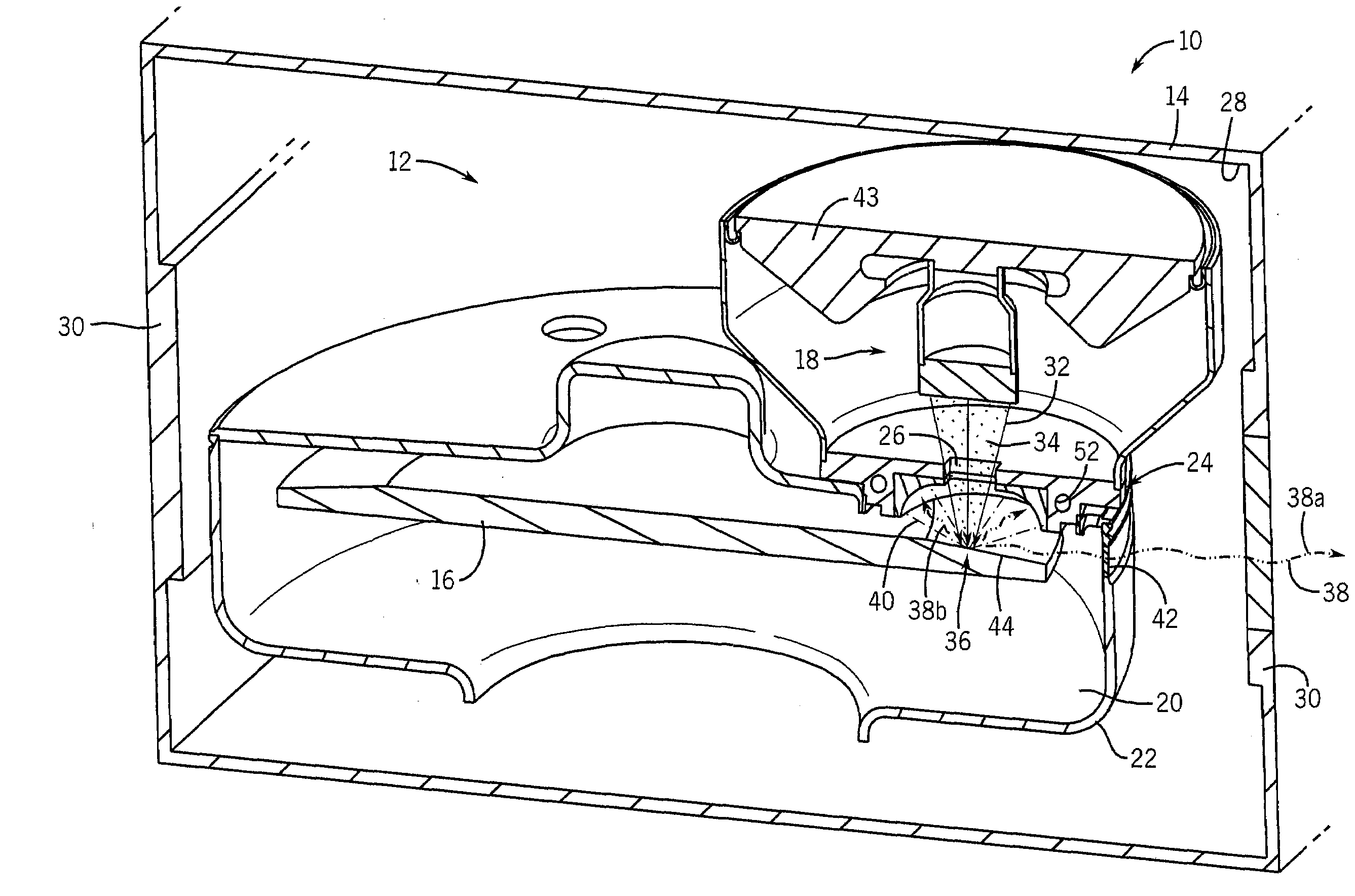
[0015]Referring to FIG. 1, a perspective sectional view of an x-ray device 10 in accordance with an embodiment is shown. The x-ray device 10 includes an x-ray tube insert 12 disposed in the schematically depicted casing 14. The x-ray tube insert 12 includes an anode 16 and a cathode assembly 18 which are at least partially disposed in a vacuum 20 within a vacuum enclosure or v...


PUM


Abstract

A shield assembly for an x-ray device is disclosed herein. The shield assembly includes a radiation shielding layer comprised of a first material. The radiation shielding layer defines a collection surface. The shield assembly also includes a thermally conductive layer attached the radiation shielding layer. The thermally conductive layer is comprised of a second material. The shield assembly also includes a passage defined by the radiation shielding layer and/or the thermally conductive layer. The passage generally conforms to the size and shape of an electron beam when it passes through the passage.

Description

FIELD OF THE INVENTION[0001]This disclosure relates generally to a shield assembly apparatus for an x-ray device.BACKGROUND OF THE INVENTION[0002]X-ray tubes generally include a cathode and an anode disposed within a vacuum vessel. The cathode is positioned at some distance from the anode, and a voltage difference is maintained therebetween. The anode includes a target track or impact zone that is generally fabricated from a refractory metal with a high atomic number, such as tungsten or any tungsten alloy. The anode is commonly stationary or a rotating disc. The cathode emits electrons that are accelerated across the potential difference and impact the target track of the anode at high velocity. As the electrons impact the target track, the kinetic energy of the electrons is converted to high-energy electromagnetic radiation, or x-rays. The electrons impacting the target track also deposit thermal energy into the anode.[0003]The x-rays are emitted in all directions. A portion of th...

Claims


Application Information

Patent Timeline
IPC IPC(8): H01J35/16G21F1/00
CPCG21F1/08G21F3/00H01J35/16H01J2235/166H01J2235/1262H01J2235/1291H01J2235/1216
Inventor ROGERS, CAREY SHAWN
Owner GENERAL ELECTRIC CO
Why Eureka
Try Eureka