Directional audio signal processing using an oversampled filterbank

a filterbank and audio signal technology, applied in the field of audio signal processing applications, can solve the problems of requiring more processing, poor b>5/b> frequency resolution, and time-domain approaches that generally provide poor performan

a filterbank and audio signal technology, applied in the field of audio signal processing applications, can solve the problems of requiring more processing, poor b>5/b> frequency resolution, and time-domain approaches that generally provide poor performan

US20080112574A1Inactive Publication Date: 2008-05-15SEMICON COMPONENTS IND LLC

Image

  • Directional audio signal processing using an oversampled filterbank
  • Directional audio signal processing using an oversampled filterbank
  • Directional audio signal processing using an oversampled filterbank

Examples


Embodiment Construction

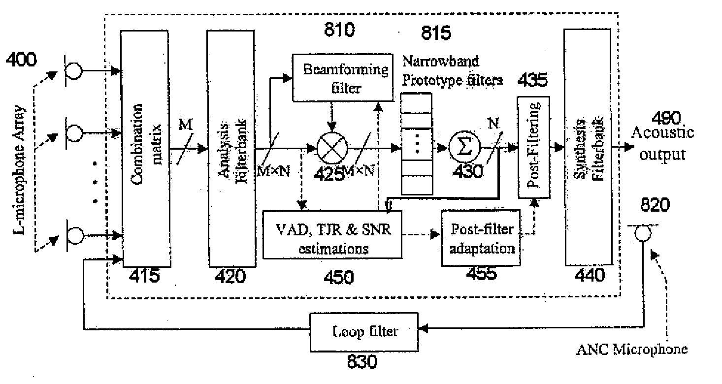
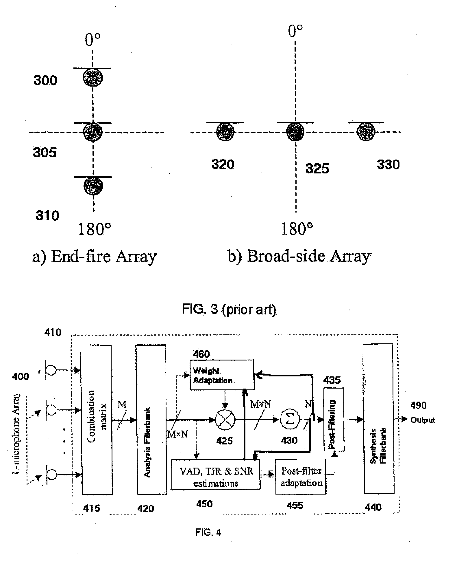
[0030] Turning now to FIG. 4 an adaptive beamformer system embodying the invention in block diagram form is shown. Note that it is assumed that the outputs of the I, microphones 400 (L≧2) are already converted to digital form by a set of analogue-to-digital converters (ADC) (not shown). Similarly, the output is assumed to be converted from digital form by an digital-to-analogue converter (DAC) (not shown) to produce an appropriate output signal 490. The digitized outputs of the L microphones 400 are first combined in a combination matrix 415. The combination matrix 415 can be any Finite Impulse Response (FIR) filter with multiple input and outputs (the number of outputs M being less or equal to the number of inputs L (M≦L)). Suitable matrices include a delay-and-sum network, a sigma-delta network and a one-to-one mapping of the inputs to the outputs (for example some general matrix through which L inputs are transformed into L (i.e. M=L) outputs)). The M outputs of the combination m...


PUM


Abstract

A directional signal processing system for beamforming information signals. The system includes an oversampled filterbank, which has an analysis filterbank for transforming the information signals in time domain into channel signals in transform domain, a synthesis filterbank and a signal processor. The signal processor processes the outputs of the analysis filterbank for beamforming the information signals. The synthesis filterbank transforms the outputs of the signal processor to a single information signal in time domain.

Description

CROSS REFERENCE TO RELATED APPLICATIONS [0001] This application claims priority to copending Canadian Patent Application entitled, “Directional Audio Signal Processing Using an Oversampled Filterbank,” having serial number 2,354,858, filed Aug. 8, 2001, which is entirely incorporated herein by reference. This application is a Continuation-In-Part application of U.S. patent application Ser. No., 10 / 214,350 filed on Aug. 7, 2002, which has been allowed and which is incorporated by reference herein in its entirety.FIELD OF THE INVENTION [0002] The present invention relates to audio signal processing applications where the direction of arrival of the audio signal(s) is the primary parameter for signal processing. The invention can be used in any application that requires the input audio signal(s) to be processed based on the spatial direction from which the signal arrives. [0003] Application of this invention includes, but is not limited to audio surveillance systems, hearing aids, voic...

Claims


Application Information

Patent Timeline
15 May 2008
Publication
US20080112574A1
IPC
H04R3/00; G10L15/20; G10L21/0232; H04R1/40; H04R25/00
CPC
H04R3/005; H04R25/507; H04R25/407; H04R25/405
Inventors
BRENNAN, ROBERT L.; CHAU, EDWARD