Engineering shape of polymeric micro- and nanoparticles

a nanoparticle and polymer technology, applied in the direction of nanoparticles, microcapsules, capsule delivery, etc., can solve the problems of phagocytosis by professional phagocytes and components of the reticuloendothelial system, impede tissue-specific targeting, and limit the half-life of micro- and nanoparticle circulation

Inactive Publication Date: 2008-05-15
RGT UNIV OF CALIFORNIA
View PDF14 Cites 49 Cited by
  • Summary
  • Abstract
  • Description
  • Claims
  • Application Information

AI Technical Summary

Benefits of technology

[0010]It is a further object of the invention to provide an improved method for producing polymeric particles in the micron and submicron size that enables manipulation of the particles into non-spherical shapes.

Problems solved by technology

The relatively few studies on particle shape are largely due to difficulties in synthesizing precisely shaped polymeric particles.
A major difficulty with the use of micro- and nanoparticles for in vivo applications such as drug delivery, immunization and diagnostics, is phagocytosis by professional phagocytes and components of the reticuloendothelial system.
Phagocytosis limits the circulation half-life of micro- and nanoparticles and impedes tissue-specific targeting.
However, these methods also suffer from drawbacks including cost, limitations on particle size, low throughput, and limited ability to sculpt particles in three dimensions.

Method used


Image

  • Engineering shape of polymeric micro- and nanoparticles
  • Engineering shape of polymeric micro- and nanoparticles
  • Engineering shape of polymeric micro- and nanoparticles

Examples


example 1

Particles Produced Using Scheme A

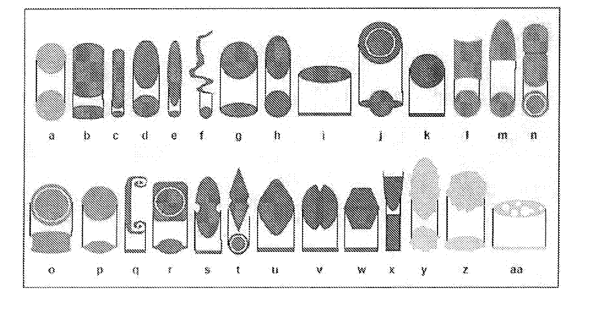
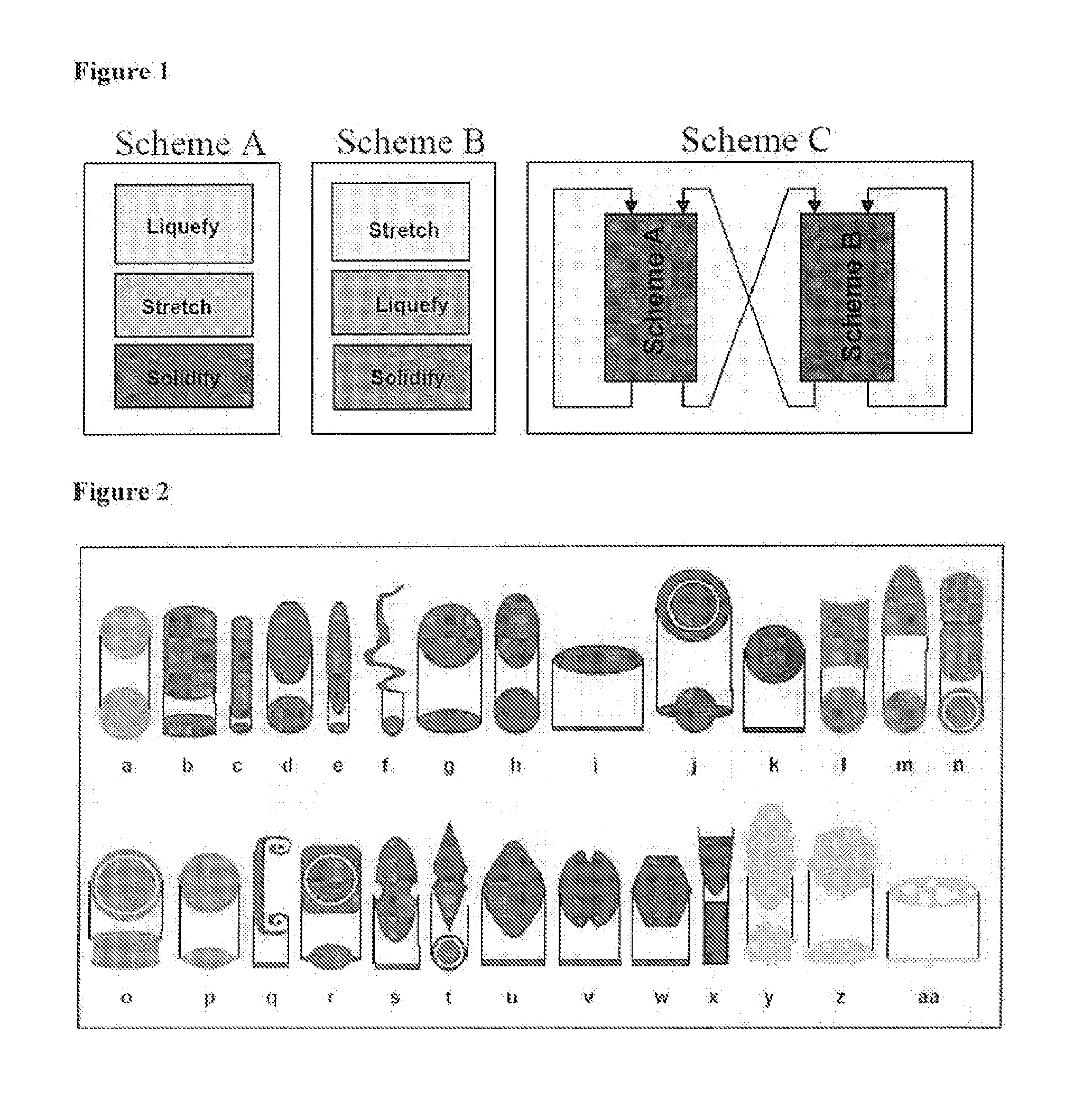
[0109]The fabrication conditions used to generate the particles discussed in this example are shown schematically in FIG. 1, Scheme A, and in Table 1.

TABLE 1Fabrication conditions for particles reported in Example 1OriginalStretchingFilmSphereAspectThicknessParticleDiameterLiquefactionRatio of(μm),Name(μm)MethodfilmPlasticizer(b)5.7120° C.235, glycerolrectangulardisks(c)0.9120° C.10.935, glycerolrectangulardisks(d) rods0.9120° C.2.470, none(e) rods0.9120° C.5.570, none(f) worms0.9155° C.8.735, glycerol(g) oblate2.9125° C.  2 (2D)35, glycerolellipses(h) prolate0.9toluene1.135, glycerolellipses(i) elliptical1.8toluene4.935, glyceroldisks(j) UFOs5.7toluene2.3 (2D)35, glycerol(k) circular2.9toluene1.9 (2D)35, glyceroldisks

[0110]Results:

[0111]Simple stretching of particles in one dimension (1-D) led to the formation of several different shapes depending on the film properties and method of liquefaction. 1-D stretching of a 35 μm thick plasticized film at ...

example 2

Particles Produced Using Scheme B

[0113]The fabrication conditions used to generate the particles discussed in this example are shown schematically in FIG. 1, Scheme B, and in Table 2.

TABLE 2Fabrication conditions for particles reported in Example 2OriginalStretchingFilmSphereAspectThicknessParticleDiameterLiquefactionRatio of(μm),Name(μm)MethodfilmPlasticizer(a) barrels2.9130° C.1.635, none(b) bullets2.9140° C.1.635, none(c) pills2.9toluene3, film35, glyceroldried offstretcher(d) pulleys9toluene1.8 (2D)35, glycerol(e) bi-convex0.9toluene1.8 (2D)35, glycerollenses

[0114]Results

[0115]1-D stretching of the film without particle-liquefaction creates an ellipsoidal void around the particle. Upon heat-induced liquefaction, polystyrene fills the void in a temperature-dependent manner. At relatively low temperatures (130° C.), the particle remains in the middle of the void and results in a barrel-like structure upon solidification with concave regions at both ends. Interestingly, liquefactio...

example 3

Particles Produced Using Scheme C

[0117]The fabrication conditions used to generate the particles discussed in this example are shown in Table 3.

TABLE 3Fabrication conditions for particles reported in Example 3OriginalStretchingFilmSphereAspectThicknessParticleDiameterRatio of(μm),Name(μm)ProcedurefilmPlasticizer(a) ribbons2.9Stretch in air, liquify4, 435,with toluene, dry inglycerolair, reinforce withPVA, stretch in air,liquefy with toluene(b) bicones0.9Start with elliptical3, 335,disks, reinforce withglycerolPVA, liquefy withtoluene, stretch(c)2.9Start with elliptical3, 235,diamonddisks, reinforce withglyceroldisksPVA, liquefy with,stretch along theminor axis oforiginal ellipticaldisks(d)2.9Stretch in air,3, 235,emarginateliquefy with toluene,glyceroldisksdry in air andisopropanol,reinforce with PVA,stretch in air perp.,liquify with toluene(e) flat pills2.9Stretch sequentially1.5, 1.5,35,along both diagonals3, 4glycerolin air, stretch alongthe length, liquefy at120° C., cool to roo...


PUM


Abstract

Compositions containing polymeric micro- and nanoparticles with non-spherical shapes and methods for making and using such particles are described herein. The particles have a size range from an average diameter of about Compositions containing polymeric micro- and nanoparticles with non-spherical shapes and methods for making and using such particles are described herein. The particles have one or more dimensions ranging from about 5 nm to about 100 μm, preferably about 100 nm to 10 μm. The particles can have any of a wide variety of non-spherical shapes. The particles are generally formed by manipulation of spherical particles embedded in a polymeric film. A wide variety of resulting shapes can be made. The resulting shape is a function of whether the films are manipulated in a first and/or second dimension, and the processes used to liquefy the microparticles. Variations of the method of manufacture may be used to generate particles having the desired shapes in large, reproducible quantities. The resulting non-spherical shaped particles can be used to alter uptake by phagocytic cells and thereby clearance by the reticuloendothelial system.

Description

CROSS-REFERENCE TO RELATED APPLICATIONS[0001]This application is a non-provisional application of U.S. Ser. No. 60 / 825,085, filed Sep. 8, 2006. The disclosure in the application listed above is herein incorporated by reference.GOVERNMENT SUPPORT[0002]The United States Government has certain rights in this invention by virtue of National Institutes of Health grant No. 1VO1 HL080718 to Samir Mitragotri.FIELD OF THE INVENTION[0003]The present invention relates to polymeric micro- and nanoparticles with non-spherical shapes.BACKGROUND OF THE INVENTION[0004]Polymeric micro and nanoparticles have found numerous applications in diverse fields such as drug delivery (Stolnick, et al, Adv. Drug Delivery Rev., 16:195-214 (1995)), advanced materials (Subramanian, et al., Adv. Mater., 11:1261-1265 (1999)), personal care (Luppi, et al., J. Pharm. Pharmacol., 56:407-411 (2004)) and medical imaging (Chen, et al., Magn. Reson. Med., 53:614-620 (2005)). Significant attention has been paid to engineer...

Claims


Application Information

Patent Timeline
Patent Type & Authority Applications(United States)
IPC IPC(8): A61K9/51C08F6/00A61K49/00A61K9/50
CPCA61K9/0097A61K9/5192A61K9/1694
Inventor MITRAGOTRI, SAMIRCHAMPION, JULIE A.KATARE, YOGESH K.
Owner RGT UNIV OF CALIFORNIA
Why Eureka
Try Eureka