Apparatus and Method for Cache Maintenance

a cache and apparatus technology, applied in the field of apparatus and cache maintenance, can solve the problems of reducing cache efficiency, affecting the efficiency of cache maintenance, and executing the branch contrary to the instruction sequence, so as to avoid cache inefficiencies, reduce weight, and avoid the effect of cache inefficiency

Inactive Publication Date: 2008-05-15
IBM CORP
View PDF39 Cites 20 Cited by
  • Summary
  • Abstract
  • Description
  • Claims
  • Application Information

AI Technical Summary

Benefits of technology

[0005]A purpose of this invention is to avoid such inefficiencies by removing trace lines experiencing early exits from the cache, thus allowing standard mechanisms to build new trace lines that better match current execution patterns. This is accomplished via a modification to the mechanism that updates the LRU (Least-Recently-Used) state of the cache line. LRU state is updated only for trace lines that execute as predicted, causing traces experiencing early exits to migrate toward the LRU position and eventually be replaced. An additional object of this invention is to optionally also update LRU state for a trace line experiencing an early exit close to the end of the trace, since the bulk of the trace is still useful.
[0006]Another purpose is to avoid inefficiencies in the cache by removing trace lines experiencing early exits from the cache, or trace lines that are short, thus allowing standard mechanisms to build new trace lines that better match current execution patterns. This is accomplished by maintaining a few bits of information about the accuracy of the control flow in a trace cache line and using that information in addition to the LRU(Least Recently Used) bits that maintain the recency information of a cache line, in order to make a replacement decision. The LRU state is updated as in a traditional cache, upon accessing a cache line. The control-flow-accuracy information for the cache line, however, is updated as execution proceeds through the path predicted by the trace cache line. In the preferred embodiment of this replacement policy, LRU bits are used to find a plurality of “less” recently used cache lines. The control-flow-accuracy and space-efficiency of each of these trace cache lines (also referred to as trace lines) is calculated using the extra bits maintained per trace line. Using a certain weighting function that in general gives lesser weight (and therefore lesser preference) to more recently used lines, the control-flow-accuracy and space-efficiency for the candidates are used to calculate their overall usefulness. The candidate cache line deemed least useful is evicted.

Problems solved by technology

However, as a program proceeds from one phase to the next, frequently the execution patterns change resulting in branch execution that is contrary to the instruction sequences stored in traces.
Other trace lines may experience continued execution, but with a mispredicted branch in the middle of the trace causing an early exit of the trace.
Since significant portions of such trace lines are not executed, the efficiency of the cache is reduced.
Moreover, since the early exit from such traces is not anticipated, branch misprediction penalties are incurred due to the delay in fetching the appropriate instructions at the target of the branch.
One limitation of trace caches is that branch prediction must be reasonably accurate before constructing traces to be stored in a trace cache.
Any instructions beyond this branch are never executed, essentially becoming unused overhead that reduces the effective utilization of the cache.
Since the branch causing the early exit is unanticipated, significant latency is encountered (branch misprediction penalty) to fetch instructions at the branch target.
With Instruction Caches that hold execution traces instead of sequential instructions as held in memory, using recency alone to qualify the usefulness of a cache line may not result in the most effective use of cache storage.
This creates the possibility that a cache line holding the instruction requested by the processor, might be available in the cache, and yet, that cache line might not represent the true execution sequence leading up to or following that instruction in the current phase the program is executing in.
The trace cache line stays in the cache longer and may lead to wasted space in the cache, since it holds possibly non-relevant paths through execution.
Performance of the processor also suffers because in trace cache designs where execution follows a trace line and predictions built in to it, with corrective action for a wrongly predicted control flow starting only after the full branch penalty is incurred.

Method used


Image

  • Apparatus and Method for Cache Maintenance
  • Apparatus and Method for Cache Maintenance
  • Apparatus and Method for Cache Maintenance

Examples


Embodiment Construction

[0014]While the present invention will be described more fully hereinafter with reference to the accompanying drawings, in which a preferred embodiment of the present invention is shown, it is to be understood at the outset of the description which follows that persons of skill in the appropriate arts may modify the invention here described while still achieving the favorable results of the invention. Accordingly, the description which follows is to be understood as being a broad, teaching disclosure directed to persons of skill in the appropriate arts, and not as limiting upon the present invention.

[0015]The term “programmed method”, as used herein, is defined to mean one or more process steps that are presently performed; or, alternatively, one or more process steps that are enabled to be performed at a future point in time. The term programmed method contemplates three alternative forms. First, a programmed method comprises presently performed process steps. Second, a programmed ...


PUM


Abstract

A single unified level one instruction cache in which some lines may contain traces and other lines in the same congruence class may contain blocks of instructions consistent with conventional cache lines. Control is exercised over which lines are contained within the cache. This invention avoids inefficiencies in the cache by removing trace lines experiencing early exits from the cache, or trace lines that are short, by maintaining a few bits of information about the accuracy of the control flow in a trace cache line and using that information in addition to the LRU (Least Recently Used) bits that maintain the recency information of a cache line, in order to make a replacement decision.

Description

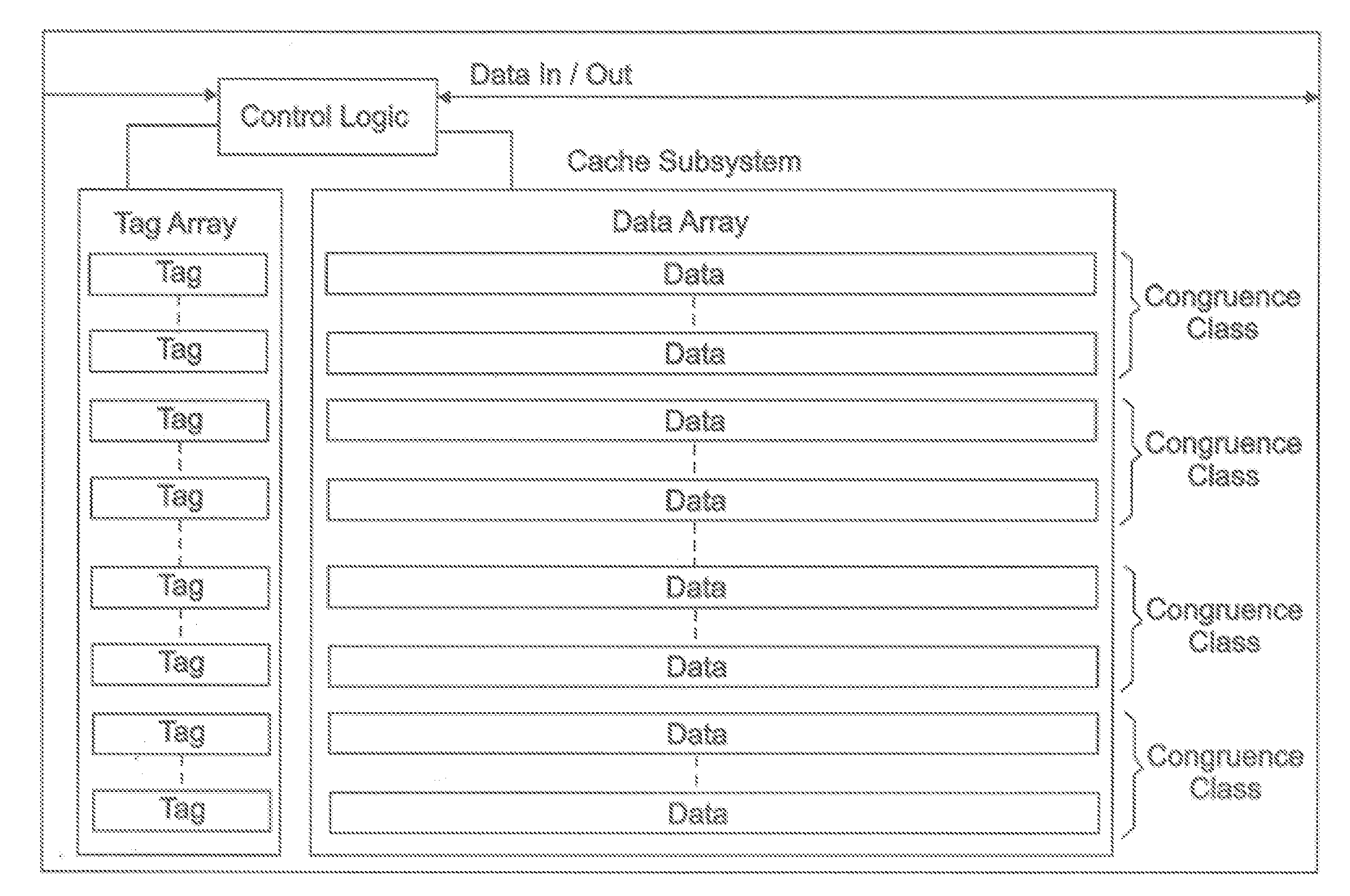
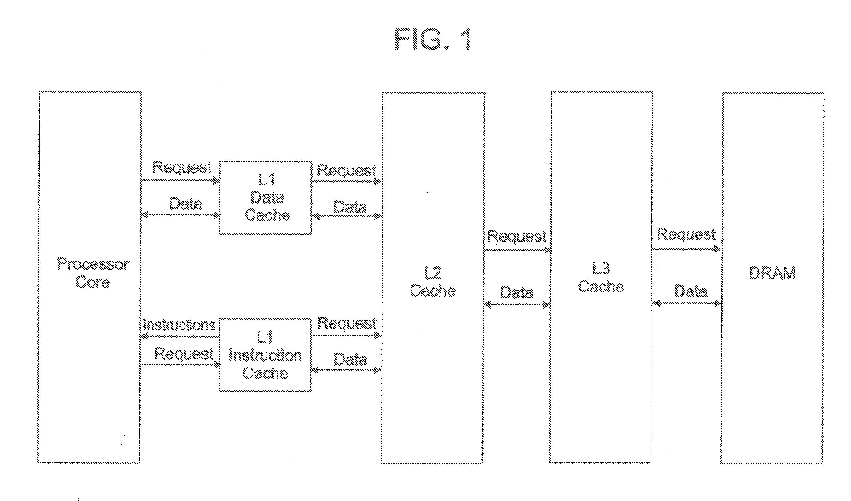
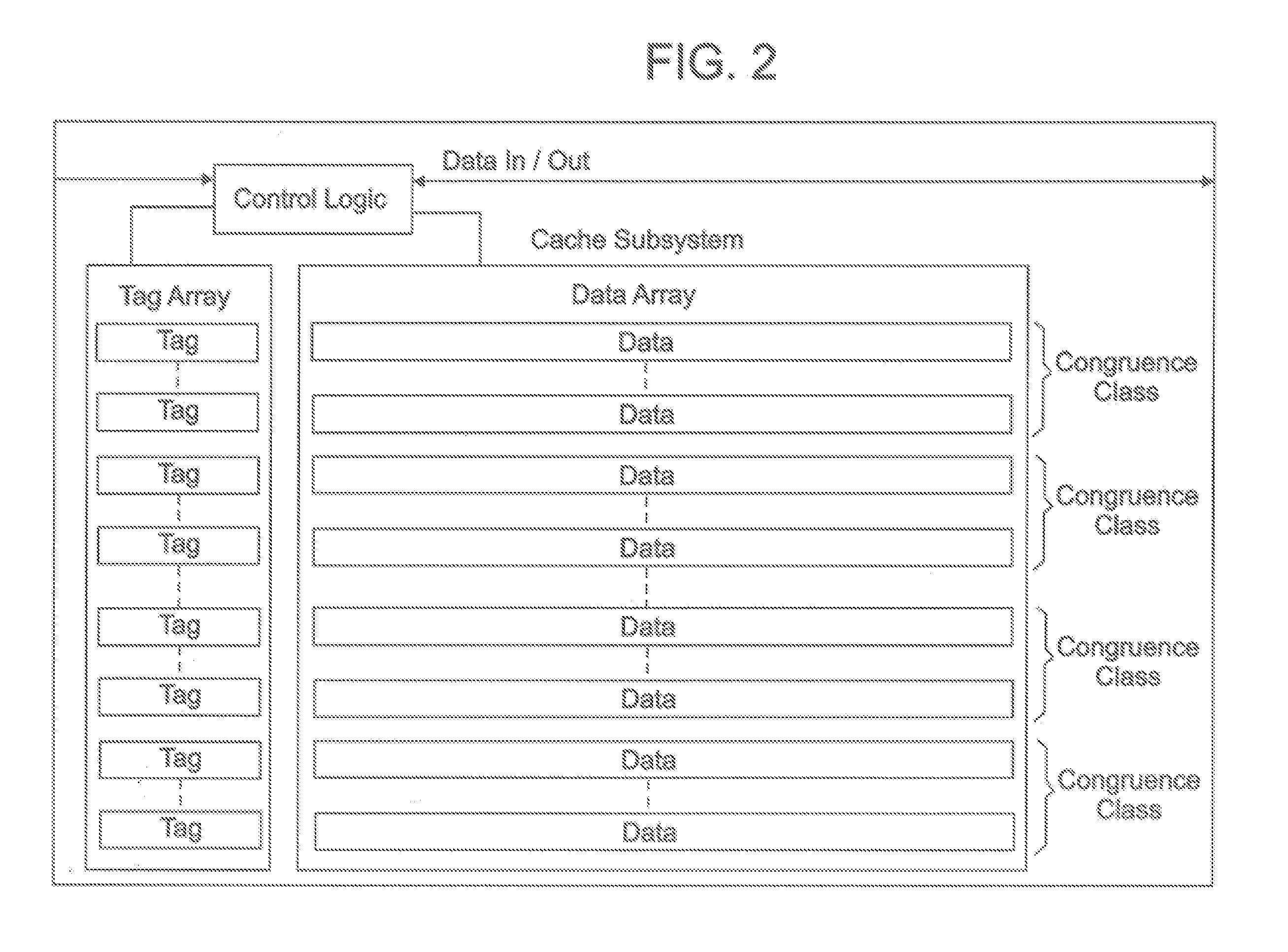
FIELD AND BACKGROUND OF INVENTION[0001]Traditional processor designs make use of various cache structures to store local copies of instructions and data in order to avoid lengthy access times of typical DRAM memory. FIG. 1 illustrates a typical cache hierarchy, where caches closer to the processor (L1) tend to be smaller and very fast, while caches closer to the DRAM (L2 or L3) tend to be significantly larger but also slower (longer access time). The larger caches tend to handle both instructions and data, while quite often a processor system will include separate data cache and instruction cache at the L1 level (i.e. closest to the processor core). All of these caches typically have similar organization as illustrated in FIG. 2, with the main difference being in specific dimensions (e.g. cache line size, number of ways per congruence class, number of congruence classes). In the case of an L1 Instruction cache, the cache is accessed either when code execution reaches the end of the ...

Claims


Application Information

Patent Timeline
Patent Type & Authority Applications(United States)
IPC IPC(8): G06F9/305
CPCG06F9/3808G06F12/0893G06F12/0862G06F9/3844
Inventor DAVIS, GORDON T.DOING, RICHARD W.JABUSCH, JOHN D.KRISHNA, M V V ANILOLSSON, BRETTROBINSON, ERIC F.SATHAYE, SUMEDH W.SUMMERS, JEFFREY R.
Owner IBM CORP
Why Eureka
Try Eureka