Method for eliminating error in camera having angular velocity detection system

a detection system and angular velocity technology, applied in the field of eliminating errors in angular velocity detection systems, can solve the problems of sensitivity error, difficulty in ensuring accuracy for all of a plurality of mass-produced objects, and none of the above-described techniques are sufficient to calibrate the inclination of angular velocity sensors with high accuracy, so as to eliminate an error in an angular velocity detection system

Inactive Publication Date: 2008-05-22
INTELLECTUAL VENTURES FUND 83 LLC
View PDF5 Cites 39 Cited by
  • Summary
  • Abstract
  • Description
  • Claims
  • Application Information

AI Technical Summary

Benefits of technology

[0007]The present invention eliminates an error in an angular velocity detection system provided in a camera, an error in the focal length of a lens, and the like.

Problems solved by technology

However, during an actual mounting process, difficulty is encountered in ensuring accuracy for all of a plurality of mass-produced articles.
However, none of the above-described techniques are sufficient for calibrating the inclinations of the angular velocity sensors with high accuracy.
Further, even when the inclinations between the angular velocity sensors and the image sensor has been calibrated, there may arise a case where another error, such as a sensitivity error or a gain error, is included in the angular velocity detection system in a combined manner.
Specifically, the angular velocity detection system is built of a sensor main body, a high-pass filter, a low-pass filter, and a detection circuit such as an amplifying circuit or the like; and includes, in a complex manner, an error in the sensitivity of the sensor main body, a gain error in an amplifying circuit, and the like.
In addition to the errors in the angular velocity sensors, an error in the focal length of the lens can also pose a problem.

Method used


Image

  • Method for eliminating error in camera having angular velocity detection system
  • Method for eliminating error in camera having angular velocity detection system
  • Method for eliminating error in camera having angular velocity detection system

Examples


Embodiment Construction

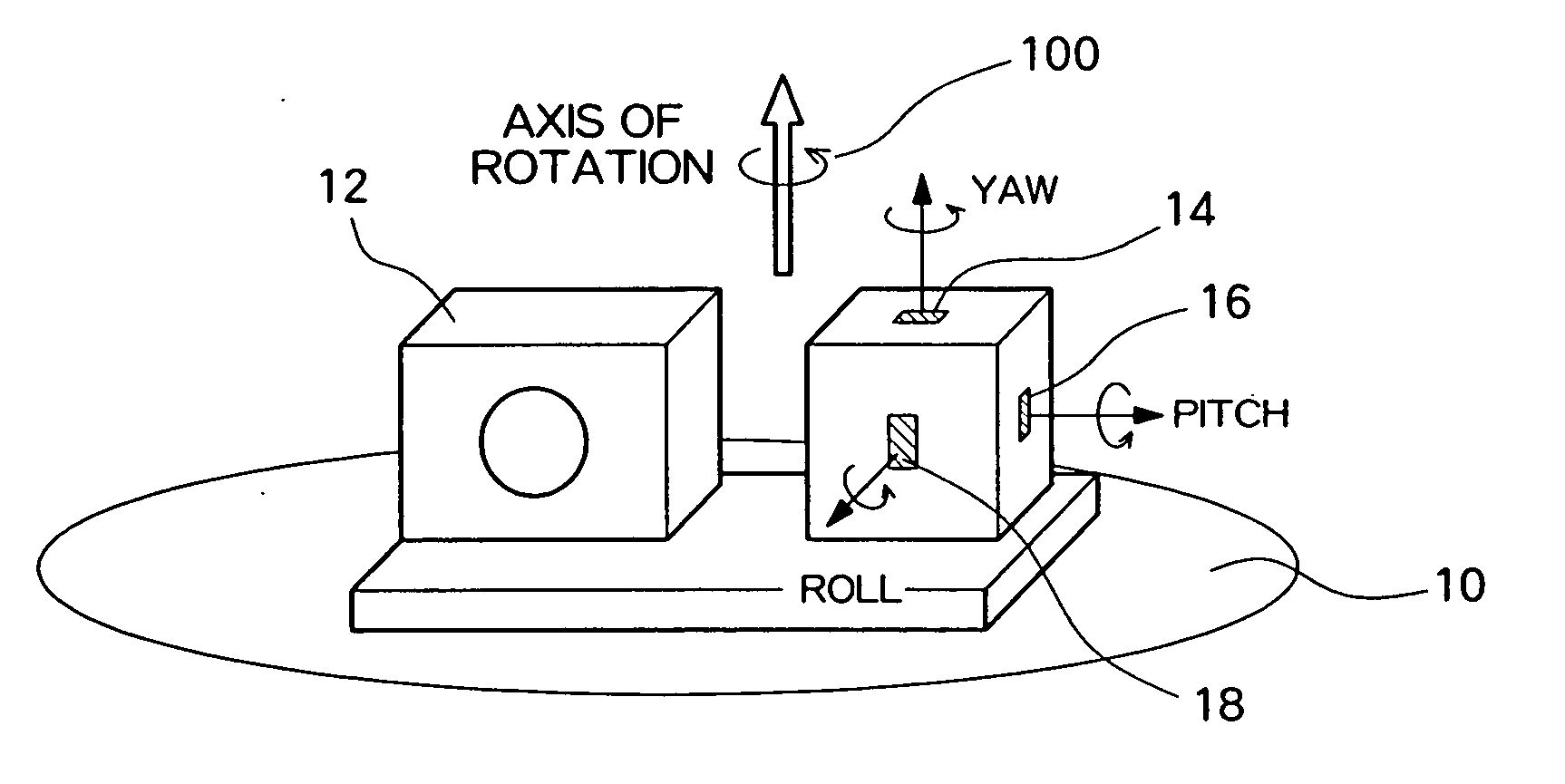
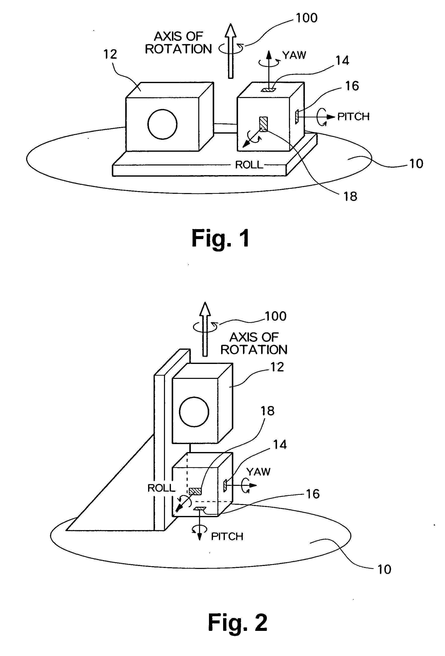
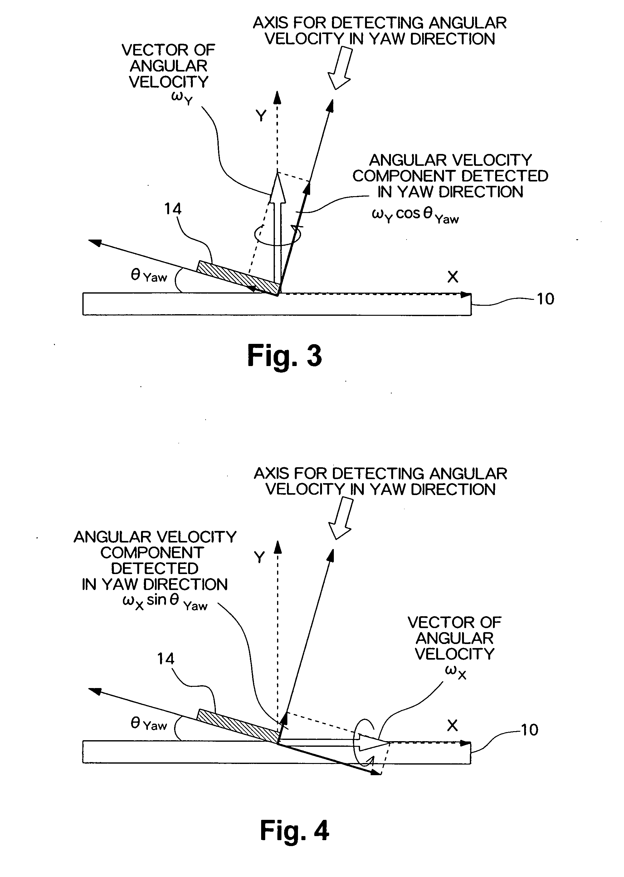
[0050]An embodiment of the present invention will be described hereunder by reference to the drawings. A camera of the present embodiment is based on the premise that both angular velocity sensors and an image sensor are inclined and that an output from the angular velocity detection system includes a plurality of errors, such as an error in the sensitivity of a sensor main body, an error in the gain of an amplification circuit, an error in the focal length of a photographing lens, and the like; calibrating inclinations of the angular velocity sensors and inclination of the image sensors will be described first, and elimination of the plurality of errors will be described next. In the present embodiment, the angular velocity detection system has an angular velocity sensor main body, a high-pass filter, a low-pass filter, and a detecting circuit including an amplification circuit and an A / D conversion circuit.

[0051]

[0052]In the present embodiment, the inclination of a gyroscopic sens...


PUM


Abstract

An error in a camera having angular velocity sensors is eliminated. A camera is placed on a rotating table and rotated, angular velocities are detected by angular velocity sensors, and a CZP chart is photographed. The motion of the camera is computed as a locus of motion of a point light source on an imaging plane from the outputs from the angular velocity sensors. The inclination of the locus motion is compared with the inclination of a zero-crossing line which has been obtained by subjecting the photographed image to Fourier transformation, to thus compute angles of relative inclination of the angular velocity sensors with respect to the image sensor. Further, when no coincidence exists between the zero-crossing line of the data into which a PSF has been Fourier-transformed and a zero-crossing line of the data into which a photographed image has been Fourier-transformed, a computer computes a correction coefficient from a proportion of an interval between the zero-crossing lines, on condition that an error is included in the angular velocity sensors or the focal length of a photographing lens, and the error is eliminated.

Description

CROSS REFERENCE TO RELATED APPLICATIONS[0001]This application claims priority to Japanese Patent Application No. 2006-310678 filed on Nov. 16, 2006, which is incorporated herein by reference in its entirety.FIELD OF THE INVENTION[0002]The present invention relates to a method for eliminating errors, such as a sensor error, an optical error, and the like, in a camera having an angular velocity detection system.BACKGROUND OF THE INVENTION[0003]When angular velocity sensors, such as gyroscopic sensors or the like, are used, locations where the angular sensors are to be mounted and mount angles must be adjusted with high accuracy. However, during an actual mounting process, difficulty is encountered in ensuring accuracy for all of a plurality of mass-produced articles. There may arise a case where inclinations occur during mounting of the angular velocity sensors, whereby outputs from the angular velocity sensors differ from values which should be output originally. In a digital camera,...

Claims


Application Information

Patent Timeline
Patent Type & Authority Applications(United States)
IPC IPC(8): G01B9/00G01P21/00
CPCG01C25/005G02B27/64H04N5/23248G06T2207/20201G06T5/003G06T2207/20056H04N5/23258H04N23/68H04N23/6812
Inventor HAINO, MASAMIMIKI, TAKANORI
Owner INTELLECTUAL VENTURES FUND 83 LLC
Why Eureka
Try Eureka