Actuating Device With Rotary Switch

a technology of rotary switch and actuating device, which is applied in the direction of mechanical control device, process and machine control, instruments, etc., can solve the problems of non-unambiguous, erroneous or non-functioning recognition of the position of the control element, and transmission non-functional

Active Publication Date: 2008-05-22
ZF FRIEDRICHSHAFEN AG
View PDF5 Cites 38 Cited by
  • Summary
  • Abstract
  • Description
  • Claims
  • Application Information

AI Technical Summary

Benefits of technology

[0017]Against this background, the object of the present invention is to provide a means for the electronic or generally by-wire actuation of a technical system, with which the drawbacks of the state of the art can be overcome. In particular, the actuating device shall make possible just as intuitive and easily understandable an actuation of the technical system as this has ever been possible in case of mechanical or electromechanical actuating elements, for exa

Problems solved by technology

However, the electric or electronic activation of such systems, which makes do without mechanical connection, leads to the circumstance that there will not be an unambiguous assignment any longer between the position of an actuating element and the state of the system that can be controlled by means of the actuating element, for example, a vehicle transmission.
For example, erroneous or non-functioning recognition of the position of the control element may be involved, with the consequence that the gear, preselected, for example, by the driver on the control element, was not recognized by the system and the corresponding control command was consequently not sent to the transmission.
For example, erroneous or non-functioning transmission of the control command between the control element and the system controlled therewith is equally imaginable as well.
However, the situation in which technical systems, for example, vehicle transmissions, adapt their operating or shifting state to changed general conditions and change it automatically even without direct action of the driver, also occurs increasingly frequently in modern motor vehicles with the complex technical systems, which are increasingly interlinked with one another.
While this

Method used


Image

  • Actuating Device With Rotary Switch
  • Actuating Device With Rotary Switch
  • Actuating Device With Rotary Switch

Examples


Embodiment Construction

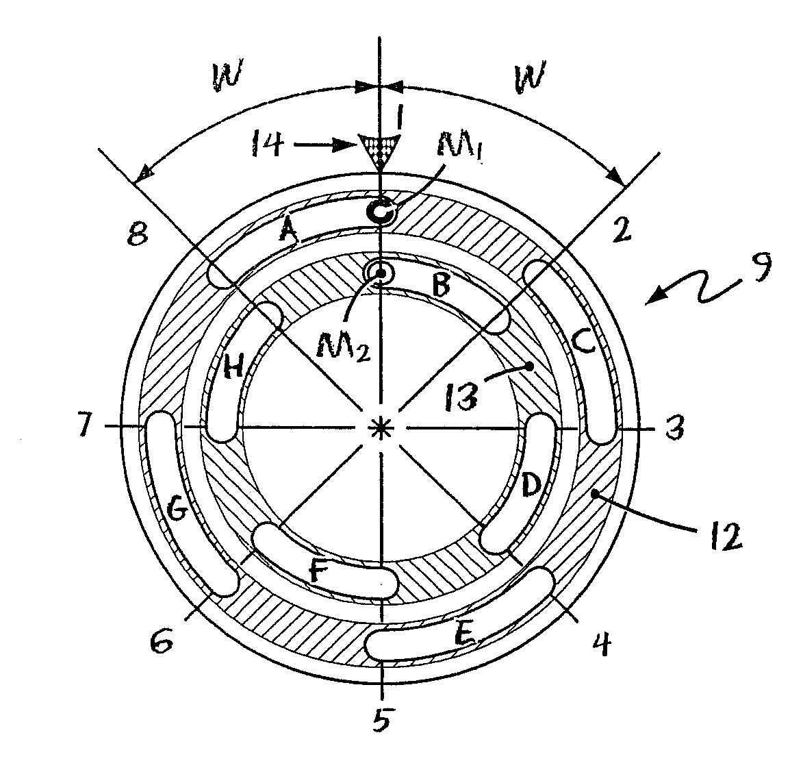
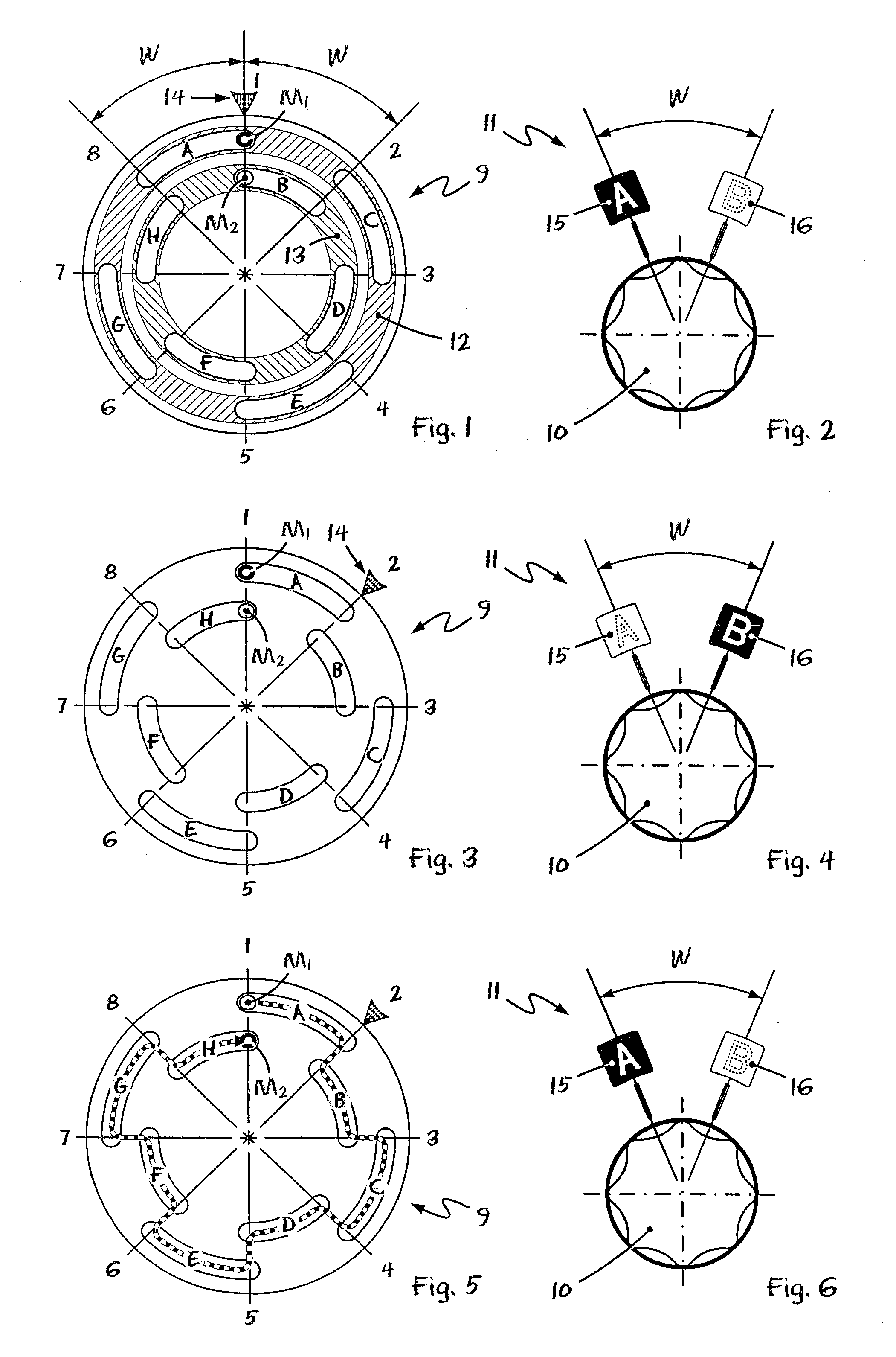
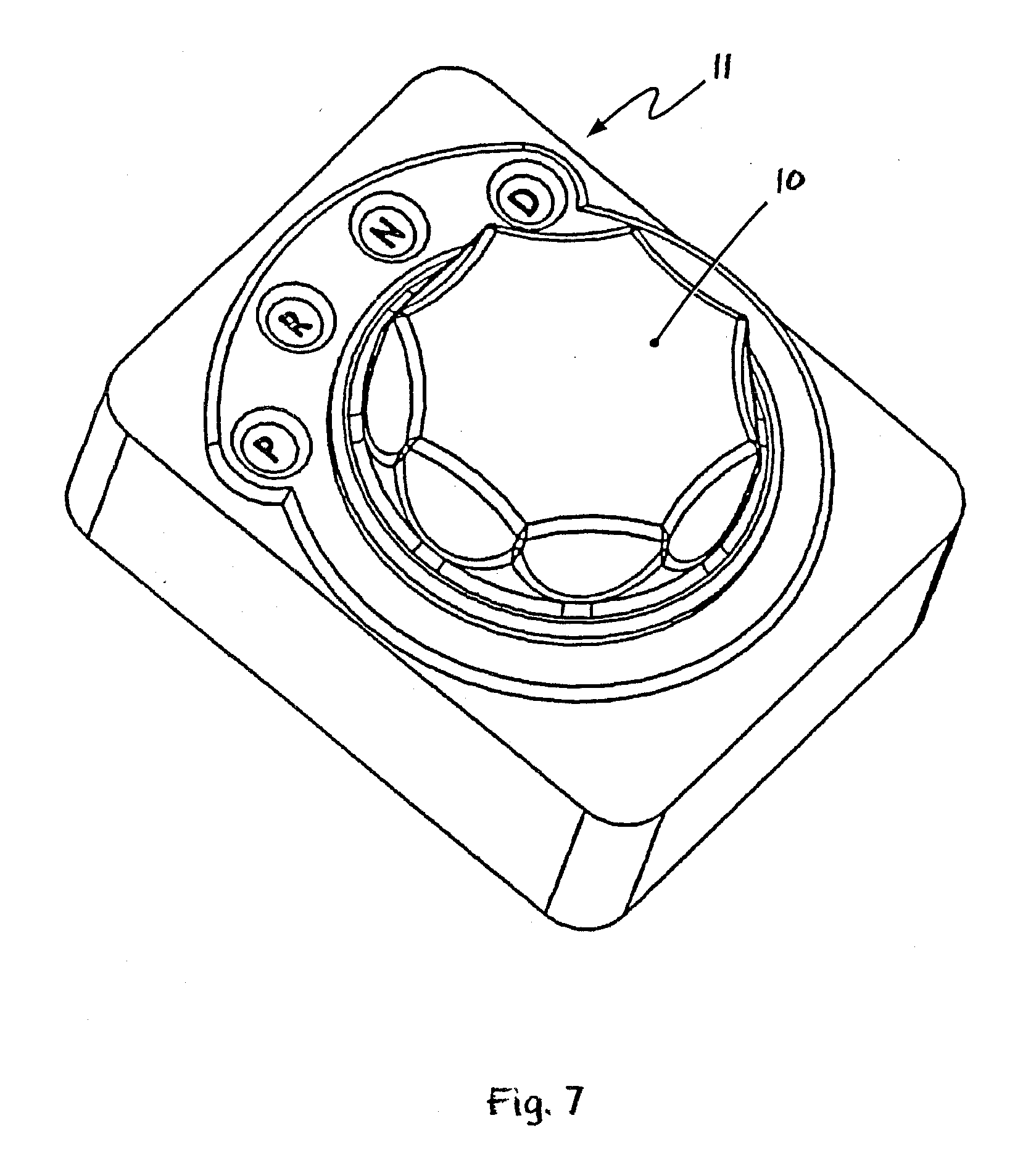
[0114]Referring to the drawings in particular, FIGS. 1 through 6 show schematic views of the crank arrangement 9 and the stop elements M1, M2 (FIGS. 1, 3 and 5) of the blocking means as well as the corresponding actuating element 10 with the display means 11 (FIGS. 2, 4 and 6) of a first embodiment of an actuating device ac cording to the present invention in different switching positions.

[0115]The actuating element, which is used to control a technical system, not shown, and is designed as a rotationally symmetrical rotary switch with recessed grips, is at first recognized on the basis of the view of the actuating element 10 in FIGS. 2, 4 and 6. It is again assumed here for the sake of simple illustration only that the rotary switch 10 being shown shall be used to turn on and off a windshield wiper.

[0116]The rotary switch 10 is located here on the axis of rotation as the crank disk 9 shown in FIGS. 1, 3 and 5 and is connected thereto in such a way that they rotate in unison. The tw...


PUM


Abstract

An actuating device is provided for selecting gears of an automatic transmission. The actuating device includes a rotatable actuating element as well as a crank arrangement (9) with stop elements (Mn) for limiting the rotation angle of the actuating element to a total switching angle. The actuating element may assume n switching positions within the total switching angle. The crank arrangement (9) has a separate stop element (Mn), which can be activated in a controlled manner, and a crank area (12, 13) for each of the n switching positions. The crank area (12, 13) comprises at least one crank segment (A, B, C, . . . ), between the end stops of which a stop element (Mn) can assume one of n relative positions, which correspond to the n switching positions. The crank segments (A, B, C, . . . ) are arranged distributed over the total crank angle such that all n relative positions are occupied by the n stop elements (Mn) for each relative switching position (1, 2, 3, . . . ). The actuating device makes possible, analogously to purely mechanical actuating elements with discrete locking position, the reliable actuation of complex technical systems. At the same time, intuitively detectable and especially tactile feedback, which is unambiguous under all operating conditions, is achieved for the actual state of the system.

Description

CROSS REFERENCE TO RELATED APPLICATIONS[0001]This application is a United States National Phase application of International Application PCT / DE2006 / 000030 and claims the benefit of priority under 35 U.S.C. § 119 of German Patent Application DE 10 2005 002 086.0 filed Jan. 14, 2005, the entire contents of which are incorporated herein by reference.FIELD OF THE INVENTION[0002]The present invention pertains to an actuating device with rotary switch for actuating a technical system such as an automotive technical system for selecting gears of a shift-by-wire gear change mechanism.BACKGROUND OF THE INVENTION[0003]Devices of this type are used, for example, but by no means exclusively, for the manual actuation of the gears or for gear preselection in gear change mechanisms of motor vehicles.[0004]Actuating device of the type mentioned in the introduction are used in motor vehicles to actuate a great variety of systems and functions of the motor vehicle. Numerous systems and functions are ...

Claims


Application Information

Patent Timeline
IPC IPC(8): G05G5/04F16H59/08
CPCB60K37/06B60K2350/102F16H59/08F16H61/24G05G1/10G05G5/005Y10T74/20085G05G5/065H01H3/50H01H2009/0083F16H2059/081F16H2061/165G05G5/04B60K2370/126B60K2370/158
Inventor GIEFER, ANDREASMEYER, JORG
Owner ZF FRIEDRICHSHAFEN AG
Why Eureka
Try Eureka