Touch panel module and method of fabricating the same

Inactive Publication Date: 2008-05-22
WINTEK CORP
View PDF25 Cites 33 Cited by
  • Summary
  • Abstract
  • Description
  • Claims
  • Application Information

AI Technical Summary

Benefits of technology

[0008]The present invention is directed to a touch panel module with an improved overall transmittance.
[0021]Since the transparent touch panel of the touch panel module according to the present invention, unlike the conventional art, is not bonded to the cover using an optically clear adhesive. As a result, when a user is using an electronic device installed with the touch panel module of the present invention, the user is able to clearly read the information displayed on the transparent touch panel of the electronic device. In other words, the touch panel module of the present invention has a better overall transmittance. Further, the thickness of the touch panel module of the present invention is comparatively thinner. In addition, the method of fabricating a touch panel module according to the present invention has a higher process yield and a higher production capacity.

Problems solved by technology

However, due to the presence of an air gap G present between the transparent part 112 and the transparent capacitive touch panel 120, the overall transmittance of the conventional touch panel module 100 is adversely affected.

Method used


Image

  • Touch panel module and method of fabricating the same
  • Touch panel module and method of fabricating the same
  • Touch panel module and method of fabricating the same

Examples


first embodiment

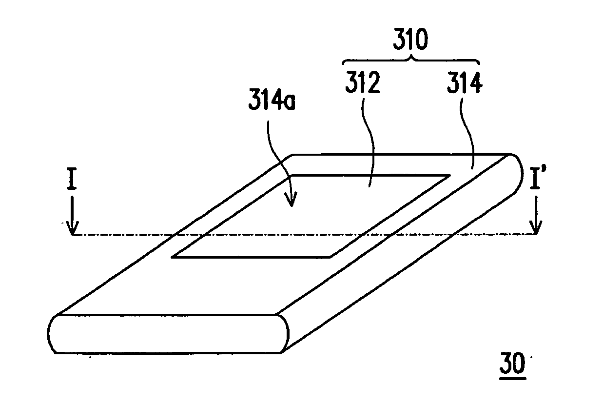
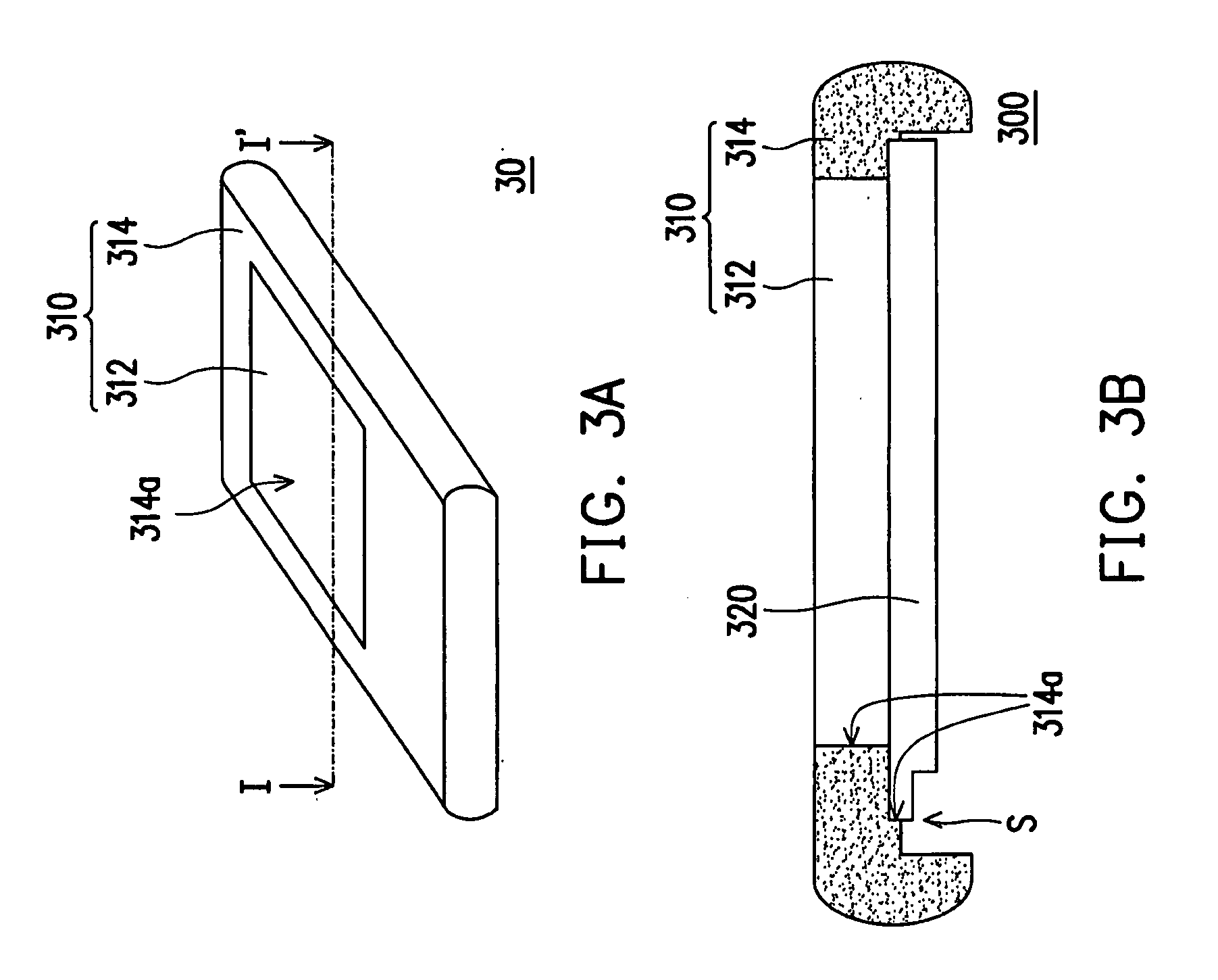
[0033]FIG. 3A is a schematic three-dimensional view illustrating an electronic device according to the first embodiment of the present invention, and FIG. 3B is a schematic cross-sectional view illustrating the electronic device shown in FIG. 3A along the line I-I′. Please refer to FIG. 3A and FIG. 3B. In the first embodiment, a touch panel module 300 that is suitable for use in an electronic device 30 is provided. Examples of the electronic device 30 include personal digital assistants, mobile phones, notebook computers or industrial control panels. The touch panel module 300 of the first embodiment includes a cover 310 and a transparent touch panel 320. At least a portion of the transparent touch panel 320 is directly connected to the cover 310. In the first embodiment, the transparent touch panel 320 may be directly inserted into the cover 310.

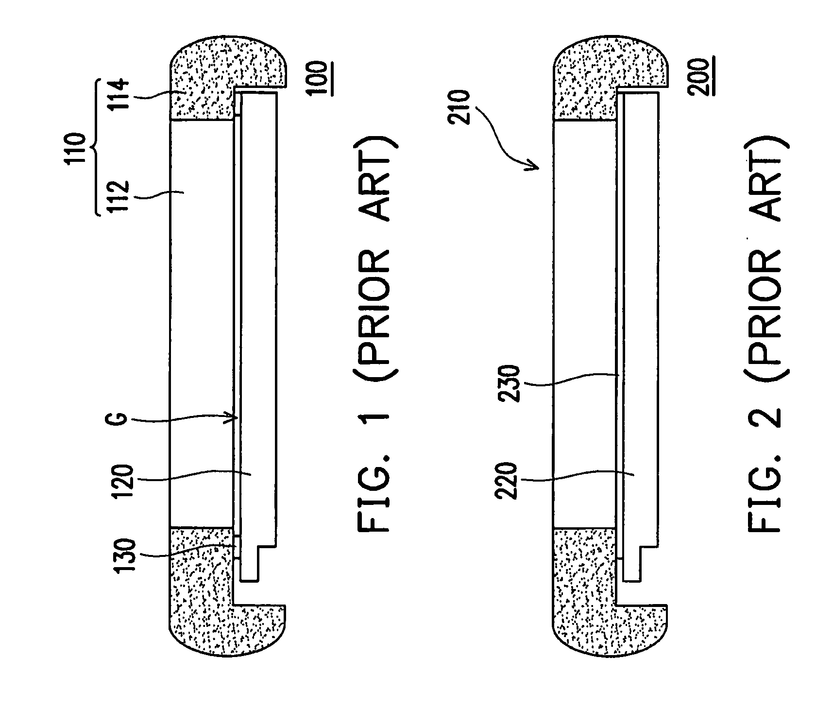
[0034]Unlike the conventional art, the transparent touch panel 320 is not bonded to the cover 310 using the optically clear adhesives 130 ...

second embodiment

[0042]Please refer to FIG. 6, which is a schematic cross-sectional view illustrating a touch panel module according to the second embodiment of the present invention. The appearance of a touch panel module 400 of the second embodiment is different from that of the touch panel module 300 of the first embodiment. In the second embodiment, a transparent part 412 of a cover 410 has a trough 412a. Further, at least a portion of a transparent touch panel 420 is directly inserted into the trough 412a. In addition, a housing 414 of the cover 410 has a hole 414a. Further, at least a portion of the transparent part 412 and at least a portion of the transparent touch panel 420 are directly inserted into the hole 414a.

[0043]The following is a description of the process for fabricating the touch panel module 400 of the second embodiment. FIG. 7A through FIG. 7C are schematic views illustrating a method of fabricating the touch panel module according to the second embodiment of the present inven...

third embodiment

[0045]Please refer to FIG. 8, which is a schematic cross-sectional view illustrating a touch panel module according to the third embodiment of the present invention. The major difference between the third embodiment and the above-mentioned embodiments is that a transparent touch panel 520 of a touch panel module 500 may be disposed on a surface 516 of a cover 510.

[0046]It should be noted that the appearance of the covers 310, 410 and 510 may be modified such as a flat plate according to the design requirement. However, the above-mentioned embodiments are merely examples used to illustrate the present invention. Hence, the present invention is not limited thereto.

[0047]In view of the above, the touch panel module and the method of fabricating the same according to the present invention have at least the following advantages:

[0048]Since the transparent touch panel of the touch panel module according to the present invention, unlike the conventional art, does not utilize an optically c...


PUM


Abstract

A touch panel module including a cover and a transparent touch panel is provided. At least a portion of the transparent touch panel is directly connected to the cover. A method of fabricating the touch panel module including the following steps is also provided. First, a transparent touch panel is provided. Next, the cover is formed using injection molding technology such that at least a portion of the transparent touch panel is directly connected to the cover.

Description

CROSS-REFERENCE TO RELATED APPLICATION[0001]This application claims the priority benefit of U.S. provisional application Ser. No. 60 / 864,975, filed on Nov. 9, 2006. The entirety of the above-mentioned patent application is hereby incorporated by reference herein and made a part of this specification.BACKGROUND OF THE INVENTION[0002]1. Field of the Invention[0003]The present invention relates to a panel module and a method of fabricating the same. More particularly, the present invention relates to a touch panel module and a method of fabricating the same.[0004]2. Description of Related Art[0005]In today's world, people are becoming more and more dependent on electronic devices. Electronic products such as notebook computers, mobile phones, personal digital assistants (PDAs), and digital walkmans are becoming indispensable in people's day-to-day life and work. The above-mentioned electronic products are all installed with a human-machine interface, and each is equipped with an intern...

Claims


Application Information

Patent Timeline
IPC IPC(8): G06F3/045G06F3/041
CPCG06F3/0412
Inventor WANG, CHUN-HAOHUANG, PING-WENLIU, CHIU-MEIYU, PHENG-CHIHHWANG, CHIN-PEI
Owner WINTEK CORP
Why Eureka
Try Eureka