
Multiple-Viewer Multiple-View Display And Display Controller

a multi-viewer, display controller technology, applied in the direction of instruments, static indicating devices, optical elements, etc., can solve the problems of increasing cost, occupying a lot of space, and providing a separate display screen for each player, so as to achieve little or no penalty, the effect of crosstalk visibl

Active Publication Date: 2008-05-22
SHARP KK
View PDF13 Cites 80 Cited by
  • Summary
  • Abstract
  • Description
  • Claims
  • Application Information

AI Technical Summary

Benefits of technology

[0052]A respective lens may be disposed at each slit. The lenses may be converging lenses, such as cylindrically converging lenses. Such an arrangement permits the use of wider slits so as to provide a brighter display. Also, the transitions between images and hence viewing windows may be made sharper, for example reducing image crosstalk.
[0054]Such an arrangement allows the scanning in of image data and the refreshing of the display at rates which are the same as or similar to known types of display. Thus, such an arrangement is compatible with known or standard image source arrangements and scanning techniques while permitting the use of wide pixels to provide a multiple viewer display with sufficiently widely spaced viewing windows.
[0061]It is thus possible to provide a display which allows different views to be viewed by different viewers. Multiple viewer displays are required to provide viewing windows or regions which are spaced sufficiently far apart to allow different viewers to be able to see the different views. The relatively wide black mask portions between horizontally adjacent pixels of the same group allow such separation to be achieved and reduce the angular viewing range or ranges within which image mixing occurs. This allows a multiple viewer display of improved performance to be achieved.
[0067]The predetermined grey level may be the same for all pixels. Such an arrangement simplifies the calculations required to reduce crosstalk as it is necessary to calculate only a single grey level to be added to all pixels. It is even possible, for some applications, for the single grey level to be predetermined and preset during manufacture of the display controller, thus further reducing the workload on the controller. The predetermined grey level may represent a maximum possible crosstalk contribution.
[0072]The function may comprise a function of the pixel value to be corrected and the value of at least one other pixel. The at least one other pixel may comprise an adjacent pixel. It has been surprisingly found that, in many applications, it is sufficient, when compensating each pixel value, to take into account only one other pixel value. This simplifies the calculations required in order to reduce the visible effects of electrical crosstalk.
[0075]It has been surprisingly found that the visibility of crosstalk, for example in the form of “ghost images”, can be reduced or eliminated by adding a masking image. Such masking images can be provided by relatively simple means and with little or no penalty in terms of cost and complication.

Problems solved by technology

These conflicting needs could be satisfied by providing two separate display devices, but this would take up extra space and would increase the cost.
Furthermore, if two separate displays were used in this example, it would be possible for the driver to see the passenger display if the driver moved his or her head, which would be distracting for the driver.
However, providing a separate display screen for each player takes up a lot of space, is costly, and is not practical for portable games.
Holographic methods of image splitting are known, but in practice these methods suffer from viewing angle problems, pseudoscopic zones and a lack of easy control of the images.
In general, however, the pixel pitch is typically defined by the required resolution specification of the display device and therefore cannot be changed.
It is not always practical or cost effective significantly to change the refractive index of the substrates, which are normally made of glass.
Reducing the thickness of the CF substrate will reduce the distance between the LCD pixels and the parallax optic, but will make the substrate correspondingly weaker.
A realistic minimum for CF substrate thickness is about 0.5 mm, but the pixel-to-parallax optic separation would still be too large for multiple viewer applications, even if a parallax optic were adhered directly to a substrate of this thickness.
However, the use of horizontally elongate pixels in these documents is either arbitrary or serves some purpose unrelated to viewing window separation.
Such displays are unsuitable for multiple viewer use because, for example, of the relatively small separation between adjacent viewing windows.
This requires the use of a relatively expensive LCD.
Also, because of light leakage within the relatively complex backlight, crosstalk performance is relatively poor.
Poor crosstalk performance leads to the disadvantages described hereinafter.
However, unless such devices were modified to change the locations of the scan line and data line devices, such an arrangement would require column-by-column refreshing, which is completely incompatible with standard scanning techniques.
Even if the locations of the scan line and data line drivers were changed by redesigning the device to permit row-by-row refreshing, the vertical (or frame) and horizontal (or line) frequencies would be incompatible with standard scanning techniques.
Thus, standard scanning methods and apparatuses could not be used with such hypothetical arrangements.
Such known arrangements are unsuitable for multiple viewer multiple view displays.
For example, the viewing windows are too small and too close together to allow different viewers to see different views.
Such a technique is effective for autostereoscopic 3D displays but may not be sufficient for multiple view displays where the different images are viewed by different observers.
Although such known techniques for reducing crosstalk between views may be sufficient for autostereoscopic 3D displays, they may not be sufficient for multiple viewer multiple view displays.
If the amount of crosstalk is too high, then this may result in a viewer being able, in at least some circumstances, to see an image not intended for that viewer.

Method used


Image

  • Multiple-Viewer Multiple-View Display And Display Controller
  • Multiple-Viewer Multiple-View Display And Display Controller
  • Multiple-Viewer Multiple-View Display And Display Controller

Examples


Embodiment Construction

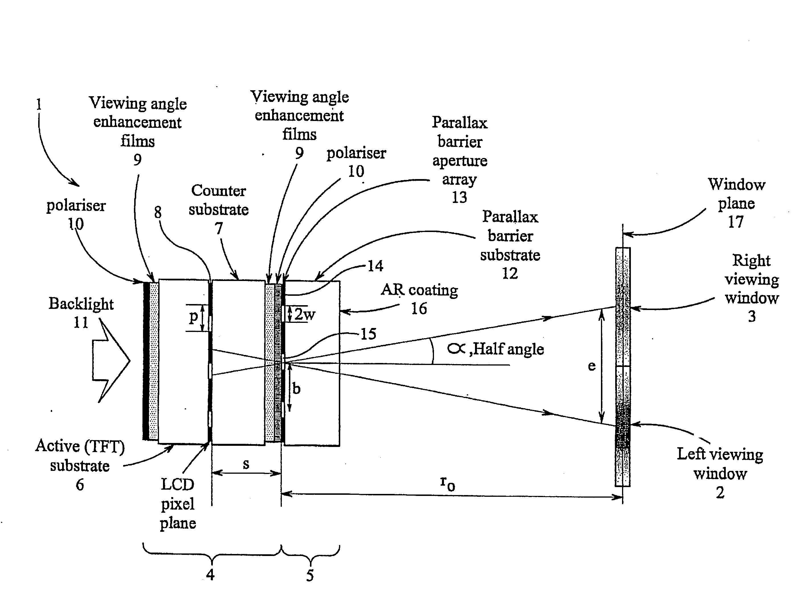
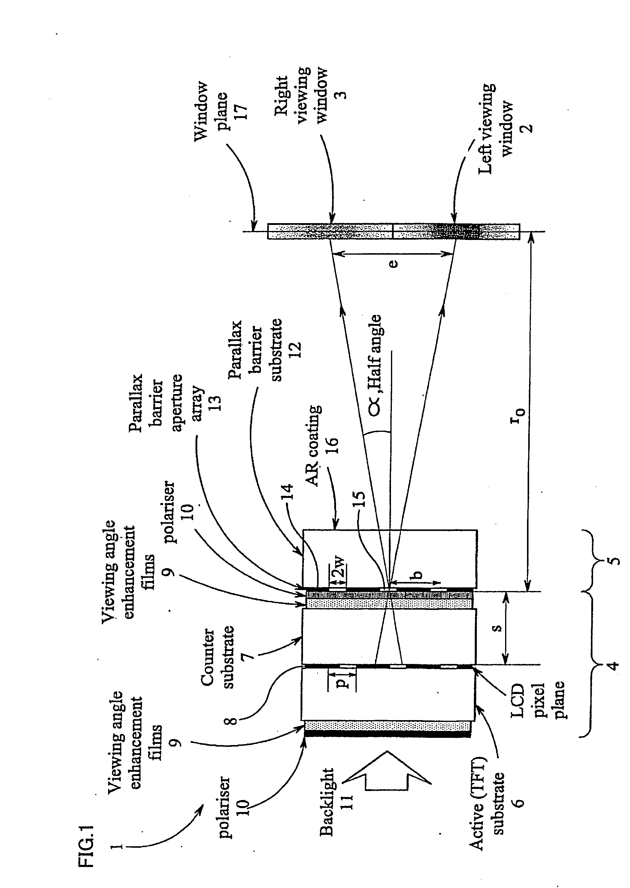
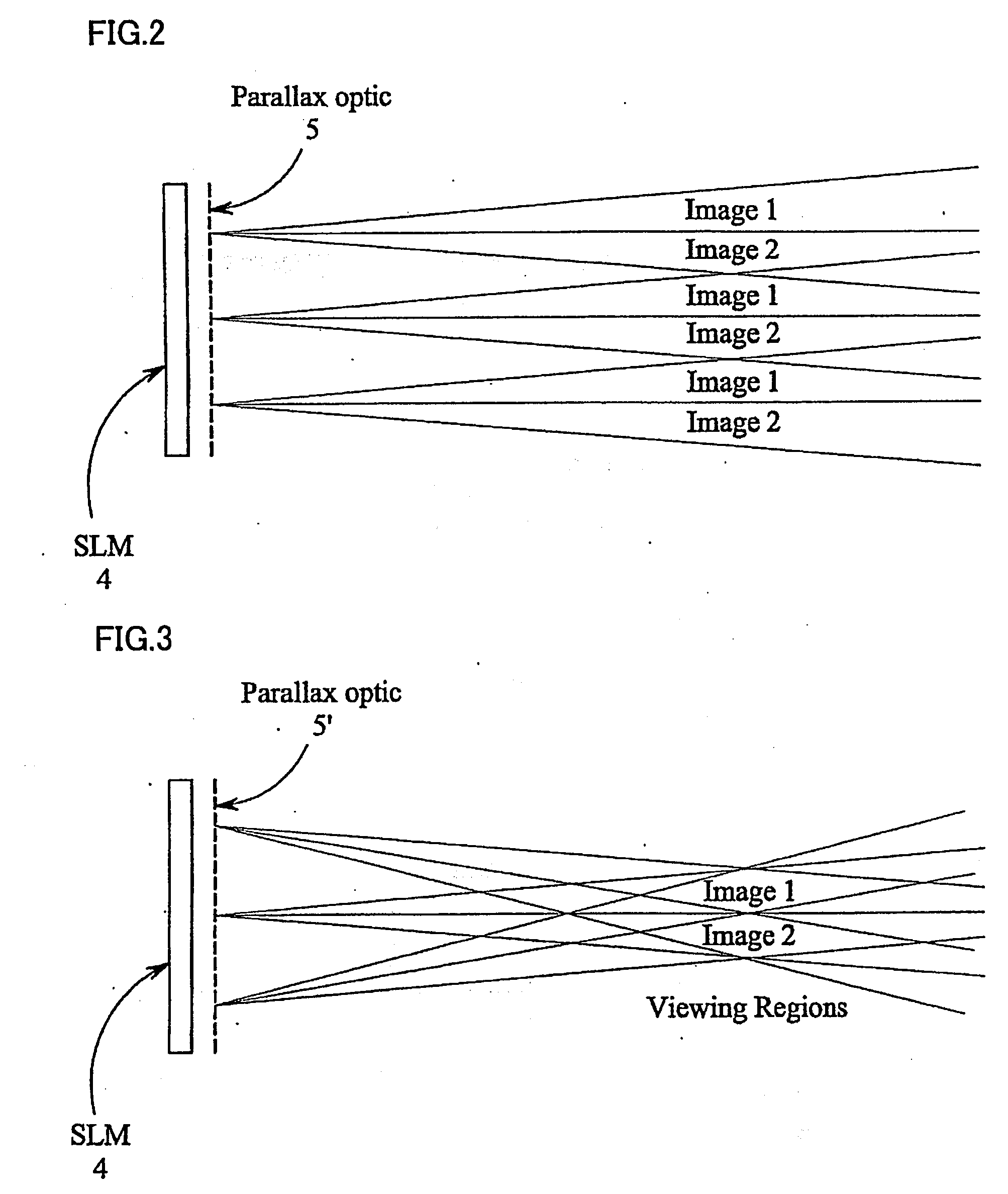
[0101]FIGS. 7 and 8 illustrate diagrammatically front and cross-sectional views of a multiple viewer multiple view display for simultaneously displaying left and right images so that these can only be seen by viewers from directions to the left and right of the normal to the display. The display comprises a spatial light modulator in the form of a transmissive liquid crystal (LC) panel 20 with a backlight (not shown) and a front parallax barrier 21. The LC panel 20 comprises substrates 22 and 23 between which are formed pixels L and R for displaying spatially multiplexed or interlaced left and right views for viewing in the directions indicated by the arrows 24 and 25, respectively. The angle between the viewing directions is indicated at θ. The parallax barrier 21 is formed on a substrate 26 so that the pixel plane of the panel 20 is disposed between the substrates 22 and 23 and the barrier plane is disposed between the substrates 22 and 26.

[0102]As shown in the front view in FIG. ...


PUM


Abstract

Techniques are disclosed for reducing the visibility of crosstalk between images in a multiple view display for simultaneously displaying two or more images independently of each other for viewing in different directions by different viewers. A multiple view display typically comprises a liquid crystal panel (20) and a parallax barrier (21) forming a dual view display for two viewers. The panel (20) comprises an array of pixels of elongate shape and arranged so as to be elongate in the horizontal direction of the normal image orientation on the panel (20). Crosstalk compensation may be provided in a display controller for the display.

Description

TECHNICAL FIELD[0001]The present invention relates to a multiple-viewer multiple-view display, which displays two or more images such that each image is visible from a different direction. The present invention also relates to a display controller.BACKGROUND ART[General Background][0002]For many years conventional single view display devices have been designed to be viewed by multiple users simultaneously. The display properties of the display device are made such that viewers can see the same good image quality from different angles with respect to the display. This is effective in applications where many users require the same information from the display, such as, for example, displays of departure information at airports and railway stations. However, there are many applications where it would be desirable for individual users to be able to see different information from the same display. For example, in a motor car or other vehicle, the driver may wish to view satellite navigat...

Claims


Application Information

Patent Timeline
IPC IPC(8): G09G5/10G09G5/00H04N13/00
CPCG09G3/003H04N13/0447H04N13/0411H04N13/0409H04N13/312H04N13/31H04N13/351
Inventor MATHER, JONATHANMONTGOMERY, DAVID J.JONES, GRAHAM R.KEAN, DIANA U.
Owner SHARP KK
Learn More