
Low Computation Mono to Stereo Conversion Using Intra-Aural Differences

Active Publication Date: 2008-05-22
TEXAS INSTR INC
View PDF11 Cites 8 Cited by
  • Summary
  • Abstract
  • Description
  • Claims
  • Application Information

AI Technical Summary

Benefits of technology

[0005]This invention decomposes the original mono signal with filters, adds intra-aural time differences (ITD) using delays and optionally attenuates or filters representing intra-aural intensity differences (IID) and mixes to stereo. These intra-aural time differences and the optional intra-aural intensity differences provide directional clues in a mono to stereo conversion with low computational cost and low distortion.
[0006]Low computation is achieved depending on the filters used. Very good stereo quality can be achieved by centering the vocal range, moving the lower frequencies to the right side and moving the higher frequencies to the left side. This is similar to many musical performance situations. If only ITD is used, there is very little distortion compared to the mono signal while still producing a realistic stereo sensation. A great deal of flexibility is available choice of the cut-off frequencies and the ITDs and optional IIDs.

Problems solved by technology

Since mono signals are more common in low-end equipment, the computational cost of the mono to stereo conversion should be at a minimum because the low-end equipment typically has limited computational capacity.

Method used


Image

  • Low Computation Mono to Stereo Conversion Using Intra-Aural Differences
  • Low Computation Mono to Stereo Conversion Using Intra-Aural Differences
  • Low Computation Mono to Stereo Conversion Using Intra-Aural Differences

Examples


embodiment 100

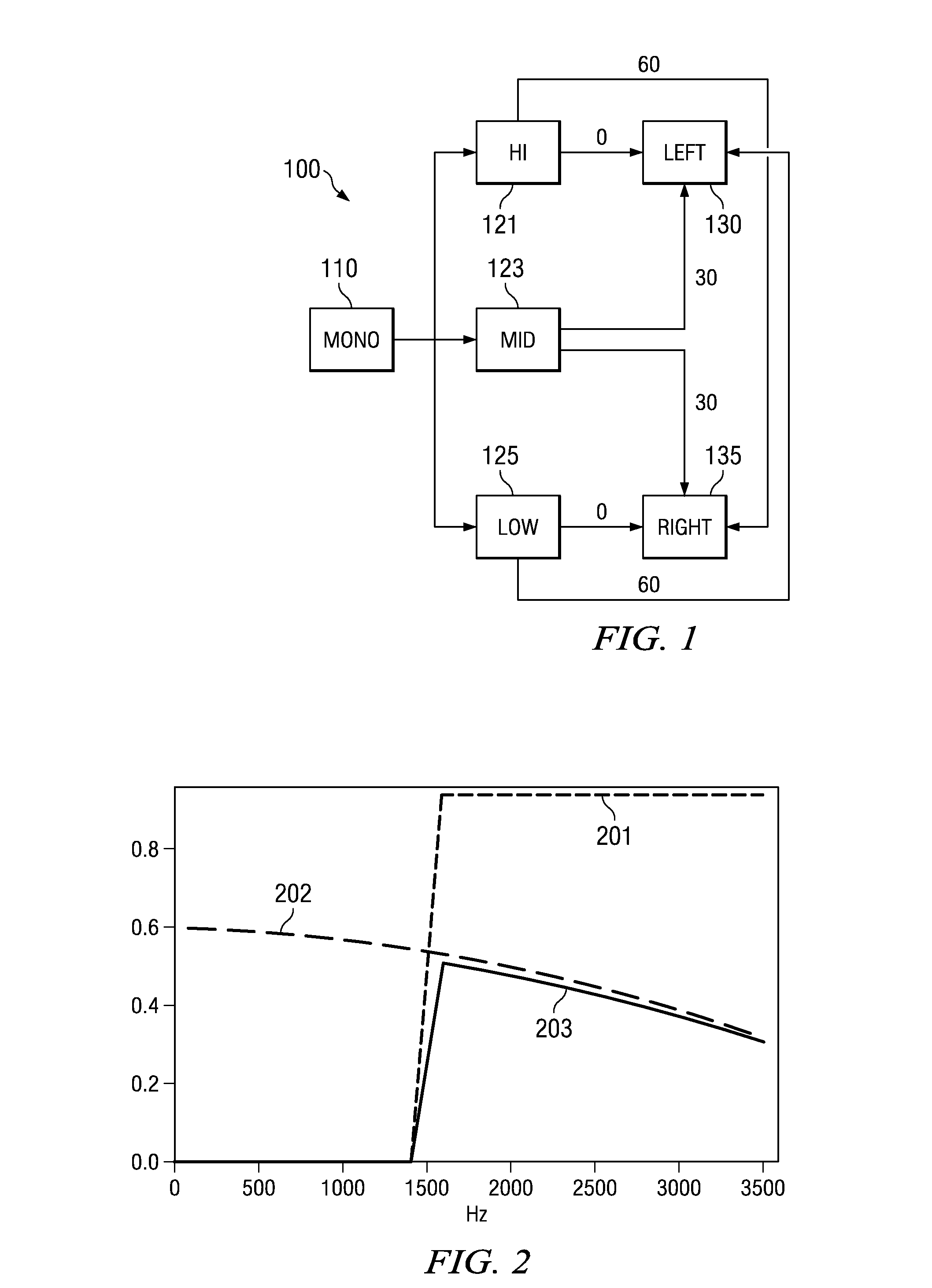
[0014]FIG. 1 illustrates a basic embodiment 100 of this invention in block diagram form. The input mono signal 110 is sampled at 44.1 KHz. Thus the Nyquist frequency was 22.05 KHz. For the experiment described below, input mono signal 110 was a produced by mixing the left and right channels of a stereo recording of a rock tune.

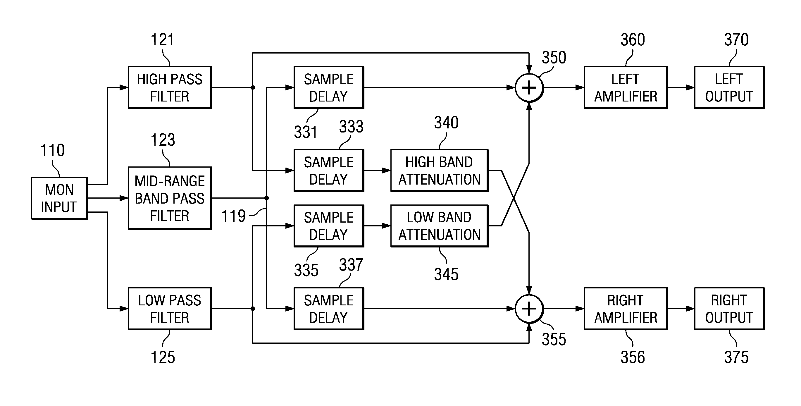
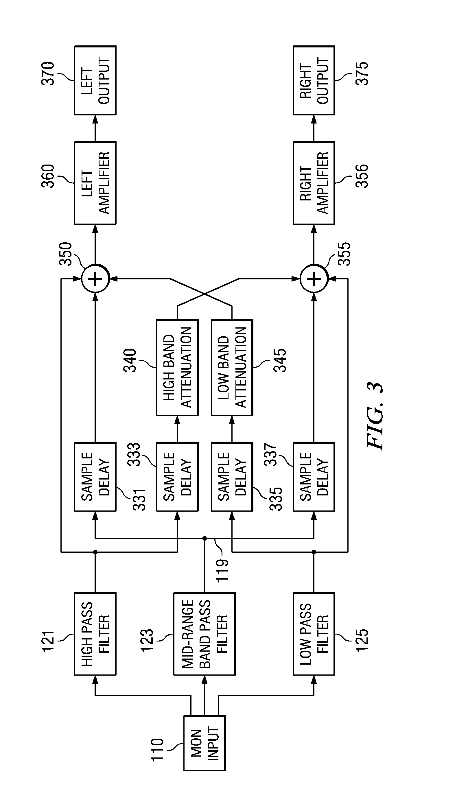
[0015]Input mono signal 110 is supplied to high-pass filter 121, mid-range band pass filter 123 and low-pass filter 125. For this experiment filters 121, 123 and 125 were embodied by 1025 tap linear phase finite impulse response (FIR) filters. Shorter, simpler infinite impulse response (IIR) filters could be used to minimize the computational cost.

[0016]Left channel 130 and right channel 135 result from summation of various delayed and undelayed signals from filters 121, 123 and 125. Left channel 130 receives an undelayed signal from high-pass filter 121. Right channel 135 receives the signal from high-pass filter 121 delayed by 60 samples, or 0.00136 seconds ...

second embodiment

[0018]If producing a realistic stereo effect is more important than approximating the original mono signal, then another technique can be used. This second embodiment adds an attenuation term the high-pass signal to the right ear to approximate the intra-aural intensity difference (IID) due to the head's attenuation of sounds from the opposite side. Likewise an attenuation term can be applied to the low-pass signal to the left ear. This attenuation is not as important since the head tends to attenuate higher frequencies more than lower ones. A simple attenuation term is the least computationally expensive, however a low-pass filter could be included to further enhance the simulated attenuation due to the head. This takes advantage of the fact that the head attenuates lower frequencies less than higher frequencies. Such a low-pass filter could be very gentle and thus could be computationally very simple.

[0019]FIG. 2 illustrates the magnitude response of the right channel according to...


PUM


Abstract

A method of converting single channel audio (mono) signals to two channel audio (stereo) signals using simple filters and an Intra-aural Time Difference (ITD) is presented. This method does not distort the spectral content of the original signal very much, and has low computation requirements. A variation is proposed which also uses Intra-aural Intensity Difference (IID).

Description

CROSS REFERENCE TO RELATED APPLICATIONS[0001]This application is related to contemporaneously filed U.S. patent application Ser. No. ______ (TI-36290) BAND-SELECTABLE STEREO SYNTHESIZER USING STRICTLY COMPLEMENTARY FILTER PAIR and U.S. patent application Ser. No. ______ (TI-37099) STEREO SYNTHESIZER USING COMB FILTERS AND INTRA-AURAL DIFFERENCES.TECHNICAL FIELD OF THE INVENTION[0002]The technical field of this invention is stereo synthesis from monaural inputs.BACKGROUND OF THE INVENTION[0003]Converting mono audio signals to stereo is a common need in current audio electronics. Two channel stereo sound is now standard. Two channel stereo generally has a much more natural and pleasant quality than mono. People naturally hear everyday sounds in stereo. There are still situations where mono sound signals exist such as telephone conversations, old recordings, low-end toys and radios etc. Converting such signals to stereo can greatly enhance their naturalness.[0004]A mono signal carries ...

Claims


Application Information

Patent Timeline
IPC IPC(8): H04R5/00
CPCH04S1/002H04S2420/03H04S5/00
Inventor TRAUTMANN, STEVEN D.TSUTSUI, RYO
Owner TEXAS INSTR INC
Learn More