Self-Contained Test Sensor

a self-contained, test sensor technology, applied in the field of diagnostic instruments, can solve the problems of generating a lot of trash, unable to automatically move or discard the strip with a device, and the insufficient sealing of the package once the first test strip is removed,

Active Publication Date: 2008-05-22
ASCENSIA DIABETES CARE HLDG AG
View PDF17 Cites 54 Cited by
  • Summary
  • Abstract
  • Description
  • Claims
  • Application Information

AI Technical Summary

Benefits of technology

[0009]According to one embodiment of the present invention, a test strip to assist in determining the concentration of an analyte in a fluid sample is disclosed. The test strip includes a base and at least one tab. The base includes an upper surface, a capillary channel, a test element, and a desiccant. The capillary channel is in fluid communication with the test element that is adapted to receive the fluid sample. The at least one tab is removably attached to the upper surface of the base. The at least one tab includes a lip that extends from the base. The lip is adapted to allow the at least one tab to be separated such that the separation from the base exposes an inlet to the capillary channel.

Problems solved by technology

One of the difficulties in designing a meter or cartridge containing multiple test stripes in a compact housing (stacked like sticks of chewing gum in a package) is how to provide the desiccation required to prevent or inhibit strip deterioration.
If the cartridge or meter itself is the primary container, the adequate resealing of the package once the first test strip is removed is a problem.
If each test strip is individually foiled, the foil (a) may get in the way of strip handling and / or (b) make it more difficult to automatically move or discard the strip with a device.
This approach generates a lot of trash from the packaging that is fed back into the strip cartridge.
This trash provides an increased likelihood of misfeeding the packaging scrap, thus, resulting in jams.
However, this approach does not provide for efficient stacking of test strips in a compact housing.
Additionally, a lot of excess packaging (the foil) is required whose removal is difficult to integrate with an automatic strip feed system.

Method used


Image

  • Self-Contained Test Sensor
  • Self-Contained Test Sensor
  • Self-Contained Test Sensor

Examples


embodiment a

Alternative Embodiment A

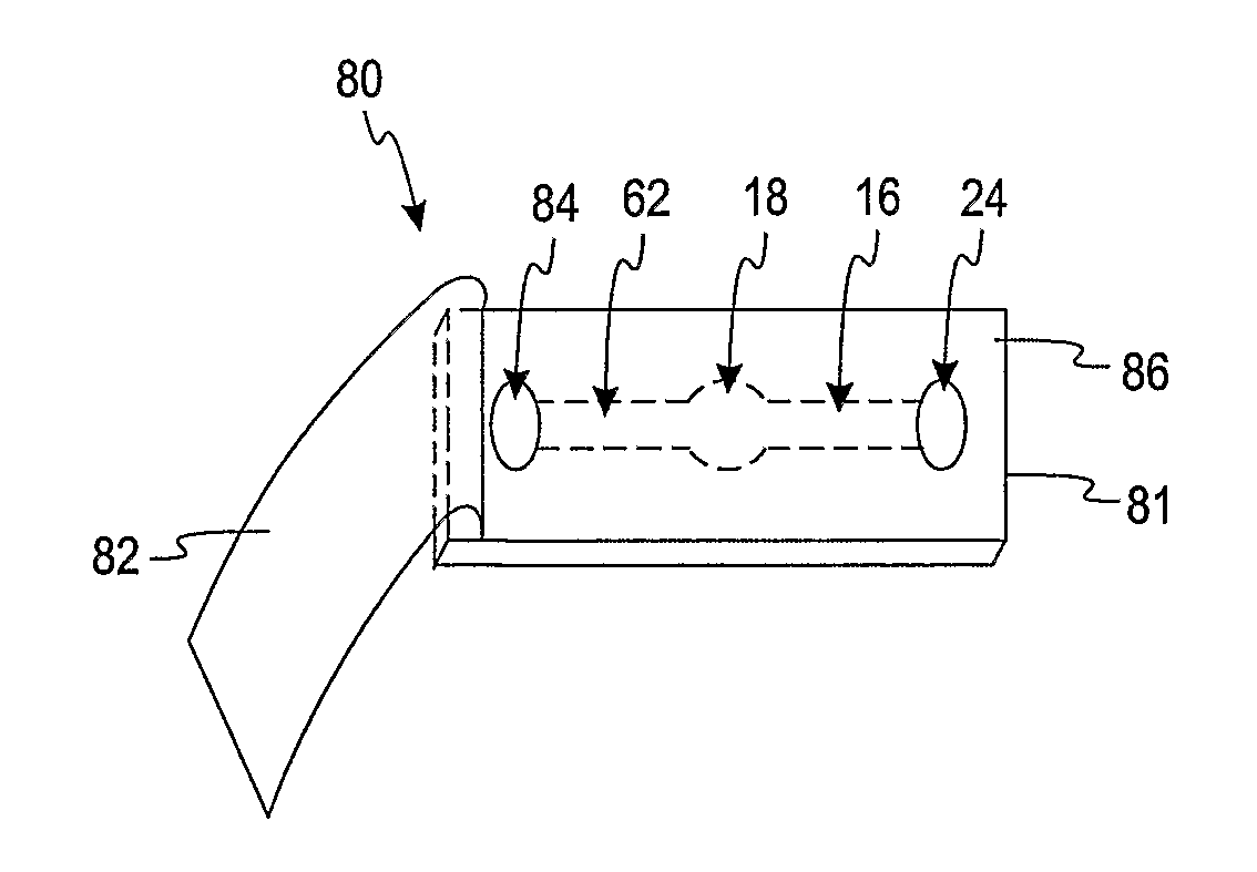
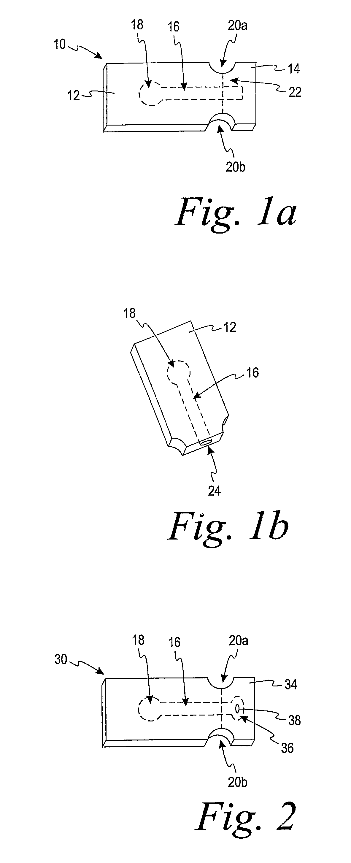
[0080]A test strip to assist in determining the concentration of an analyte in a fluid sample, comprising:

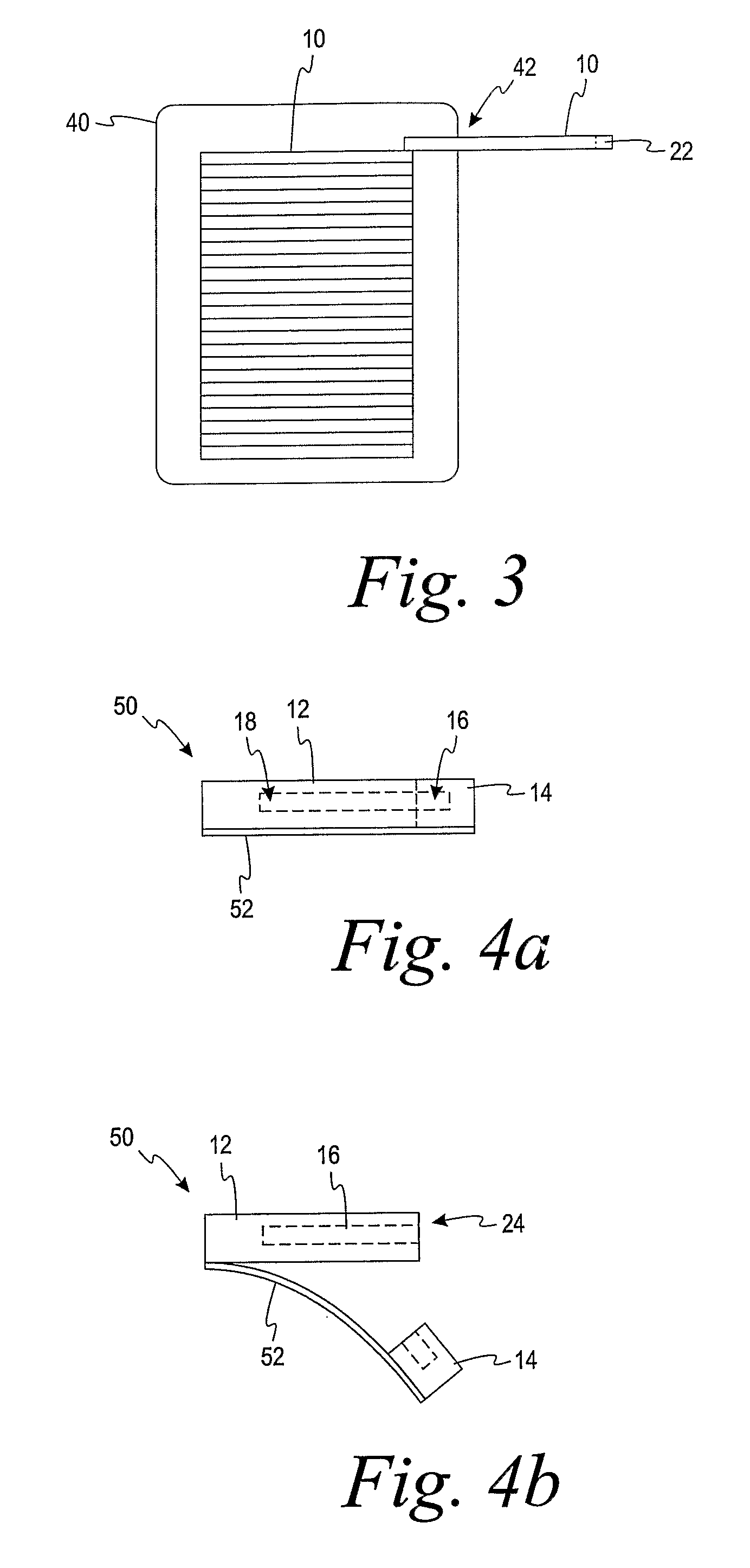
[0081]a base including a capillary channel and a test element, the capillary channel being in fluid communication with the test element, the test element being adapted to receive the fluid sample;

[0082]at least one tab removably attached to the base, the capillary channel extending from the base into a portion of the tab; and

[0083]a break line intersecting the capillary channel, wherein an inlet to the capillary channel is exposed along the break line when the tab is separated from the base.

embodiment b

Alternative Embodiment B

[0084]The test strip of Alternative Embodiment A further comprising at least one recess located between the base and the at least one tab, the at least one recess being adapted to facilitate the separation of the at least one tab from the base along the break line.

embodiment c

Alternative Embodiment C

[0085]The test strip of Alternative Embodiment B further comprising a second recess located between the base and the at least one tab opposite the at least one recess, the at least one recess and second recess facilitating the separation of the at least one tab from the base along the break line.


PUM


Abstract

A test strip to assist in determining the concentration of an analyte in a fluid sample comprises a base, at least one tab and a break line. The base includes a capillary channel and a test element. The capillary channel is in fluid communication with the test element. The test element is adapted to receive the fluid sample. The at least one tab is removably attached to the base. The capillary channel extends from the base into a portion of the tab. The break line intersects the capillary channel in which an inlet to the capillary channel is exposed along the break line when the tab is separated from the base.

Description

FIELD OF THE INVENTION[0001]The present invention relates generally to diagnostic instruments and, more particularly, to individually desiccated diagnostic test strips and a method for using the same.BACKGROUND OF THE INVENTION[0002]Test strips (e.g., biosensors) containing reagents are often used in assays for determining the analyte concentration in a fluid sample. The quantitative determination of analytes in body fluids is of great importance in the diagnoses and maintenance of certain physiological abnormalities. For example, lactate, cholesterol, and bilirubin should be monitored in certain individuals. In particular, determining glucose in body fluids is important to diabetic individuals who must frequently check the glucose level in their body fluids to regulate the glucose intake in their diets. Each test requires that a new test sensor be used, and thus, a number of test strips may be used in a single day. Cartridges that contain a number of test strips are used to allow u...

Claims


Application Information

Patent Timeline
Patent Type & Authority Applications(United States)
IPC IPC(8): B01J19/00
CPCA61B10/0045G01N33/521B01L3/502715B01L2200/0684B01L2200/141B01L2300/041B01L2300/0825B01L2400/0406G01N33/558B01L3/502B01L3/502707G01N35/00C12Q1/54C12Q1/60C12Q1/61A61B10/007B01L2300/044
Inventor FLEMING, ROGER
Owner ASCENSIA DIABETES CARE HLDG AG
Why Eureka
Try Eureka