Fuel cell stack and fuel cell device including the same

a fuel cell and stack technology, applied in the direction of cell components, electrochemical generators, cell component details, etc., can solve the problem of not being suitable for a small-size fuel cell devi

Inactive Publication Date: 2008-05-22
TOTO LTD
View PDF4 Cites 19 Cited by
  • Summary
  • Abstract
  • Description
  • Claims
  • Application Information

AI Technical Summary

Benefits of technology

[0020]As explained above, the fuel cell stack and the fuel cell device including such a fuel cell stack according to the present invention can easily make any electrical parallel and series connections of the fuel cell bodies.

Problems solved by technology

These approaches are suitable to a large-size fuel cell device having many fuel cells electrically connected to each other in parallel, but not suitable to a small-size fuel cell device.

Method used


Image

  • Fuel cell stack and fuel cell device including the same
  • Fuel cell stack and fuel cell device including the same
  • Fuel cell stack and fuel cell device including the same

Examples


third embodiment

[0083]Next, referring to FIG. 13, the fuel cell device according to the present invention will be explained. FIG. 13 is a schematically plan view thereof.

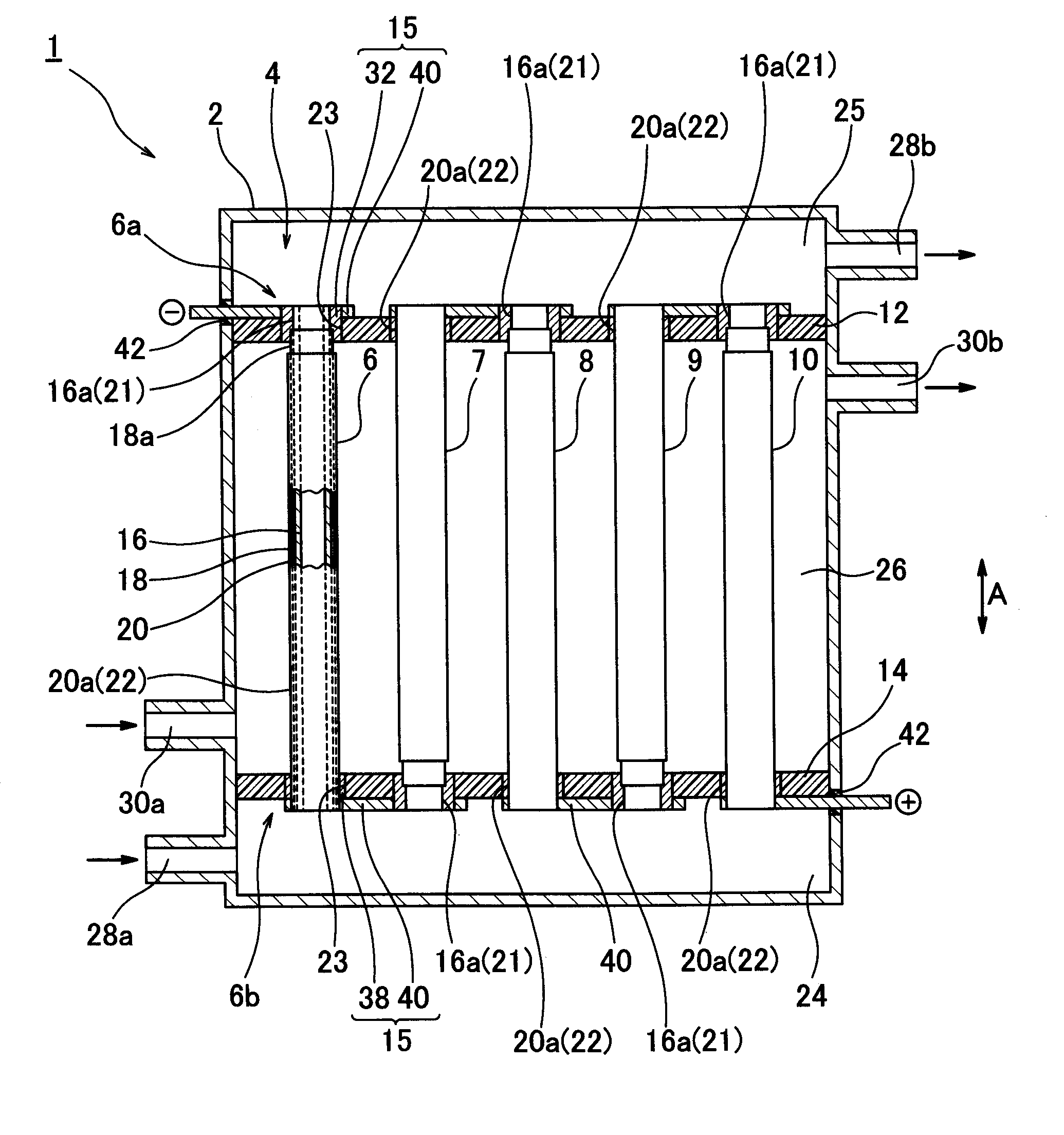
[0084]As shown in FIG. 13, five tubular fuel cell bodies having a peripheral surface and laterally arranged in a fuel cell device 80 which is the third embodiment of the present invention are obtained by replacing the five fuel cells 6-10 in the fuel cell device 1 according to the first embodiment of the present invention with five fuel cell bodies 81, in each of which two fuel cells are arranged in the longitudinal direction A and electrically connected in a series.

[0085]Now, these fuel cell bodies 81 will be explained.

first embodiment

[0086]Each of the fuel cell bodies 81 has two fuel cells 82, 84 coupled to each other in the longitudinal direction A and electrically connected to each other in a series, and a coupling member 86 coupling one (referred to other later) end 82b of the fuel cell 82 and one end 84a of the fuel cell 84. Since each of the fuel cells 82, 84 has the same components as those in the fuel cell 6 in the fuel cell device 1 according to the present invention, the components of the fuel cells 82, 84 are indicated by the same reference numbers as those of the components in the fuel cell 6 and explanations of the former components are omitted. It should be noted that the other end 82b of the fuel cell 82 corresponds to the other end 6b of the fuel cell 6 and the one end 84a of the fuel cell 84 corresponds to the one end 6a of the fuel cell 6.

[0087]The coupling member 86 is tubular and disposed so that it encloses the other end 82b of the fuel cell 82 and the one end 84a of the fuel cell 84. The cou...


PUM

PropertyMeasurementUnit
thicknessaaaaaaaaaa
thicknessaaaaaaaaaa
thicknessaaaaaaaaaa

Abstract

The present invention relates to a fuel cell stack incorporated in a fuel cell device and a fuel cell device including such a fuel cell stack. The fuel cell stack (4) according to the present invention has a plurality of tubular fuel cell bodies (6-10) arranged laterally relative to a longitudinal direction of the fuel cell bodies and electrically insulating support plates (12, 14) fixed to respective opposite ends (6a, 6b) of the plurality of the fuel cell bodies (6-10). Each of the fuel cell bodies (6-10) has an inner electrode layer (16), an outer electrode layer (20) and an electrolyte layer (18) disposed between the inner and outer electrode layers (16, 20). Each of the fuel cell bodies (6-10) also has, at one end thereof, an inner electrode exposed periphery (16a) where the inner electrode layer (16) is exposed out of the electrolyte layer (18) and the outer electrode layer (20). The fuel cell stack (4) further has connections (15) disposed at each of the support plates (12, 14) to electrically connect the fuel cell bodies (6-10) in an arbitrary combination.

Description

FIELD OF THE INVENTION[0001]The present invention relates to a fuel cell stack used in a solid-oxide fuel cell (SOFC) and a fuel cell device including such a fuel cell stack, and more specifically, to a fuel cell stack having a tubular fuel cell and a fuel cell device including such a fuel cell stack.BACKGROUND OF THE INVENTION[0002]Conventionally, a fuel cell stack having a tubular fuel cell has been known as shown, for example, in FIGS. 5-7 in Japanese Patent Laid-open Publication No. 2002-289249 and in FIGS. 1 and 6 in Japanese Patent Laid-open Publication No. 5-101842. Now, referring to FIGS. 14-16, an example of a conventional fuel cell stack described in the Japanese Patent Laid-open Publication No. 2002-289249 will be explained. FIG. 14 is a schematically perspective view of a conventional fuel cell stack, FIG. 15 is a schematically perspective view of another conventional fuel cell stack, and FIG. 16 is a perspective view of a conventional fuel cell stack assembly.[0003]As s...

Claims


Application Information

Patent Timeline
Patent Type & Authority Applications(United States)
IPC IPC(8): H01M8/02H01M8/24H01M8/10
CPCH01M8/0252H01M8/0297Y02E60/525H01M8/243Y02E60/521H01M8/1213Y02E60/50H01M8/0271
Inventor KAWAKAMI, AKIRAWATANABE, NAOKI
Owner TOTO LTD
Why Eureka
Try Eureka