Antenna Diversity Arrangement and Method
a diversity arrangement and antenna technology, applied in diversity/multi-antenna systems, wireless communication, wireless communication services, etc., can solve the problems of high cost of feeders, increased site costs, and increased costs of sites, so as to reduce the number of feeders
- Summary
- Abstract
- Description
- Claims
- Application Information
AI Technical Summary
Benefits of technology
Problems solved by technology
Method used
Image
Examples
first embodiment
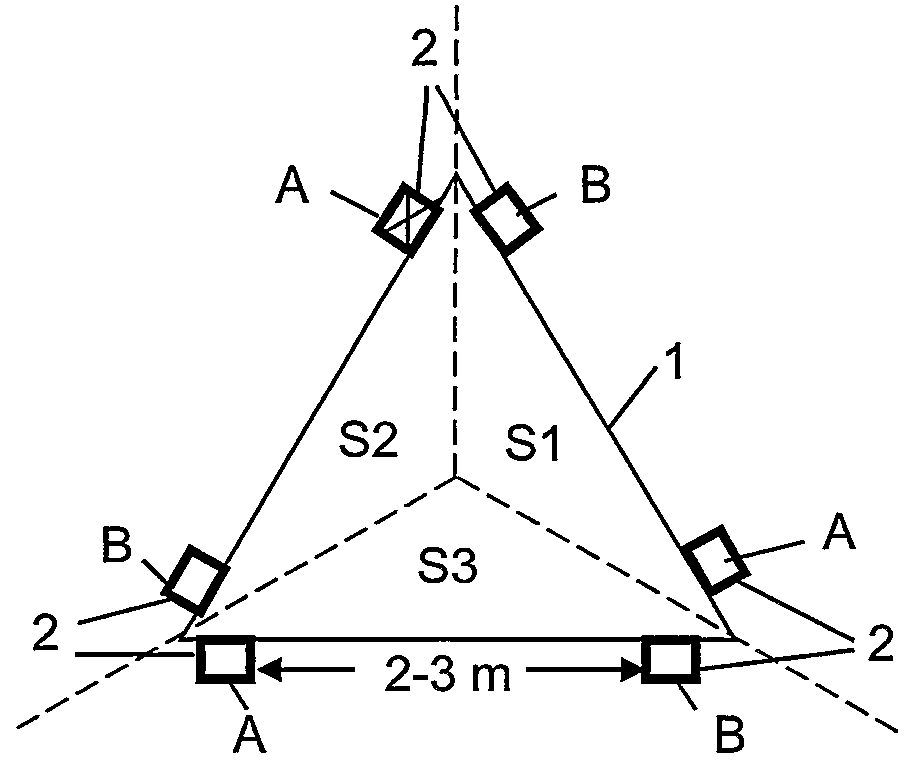
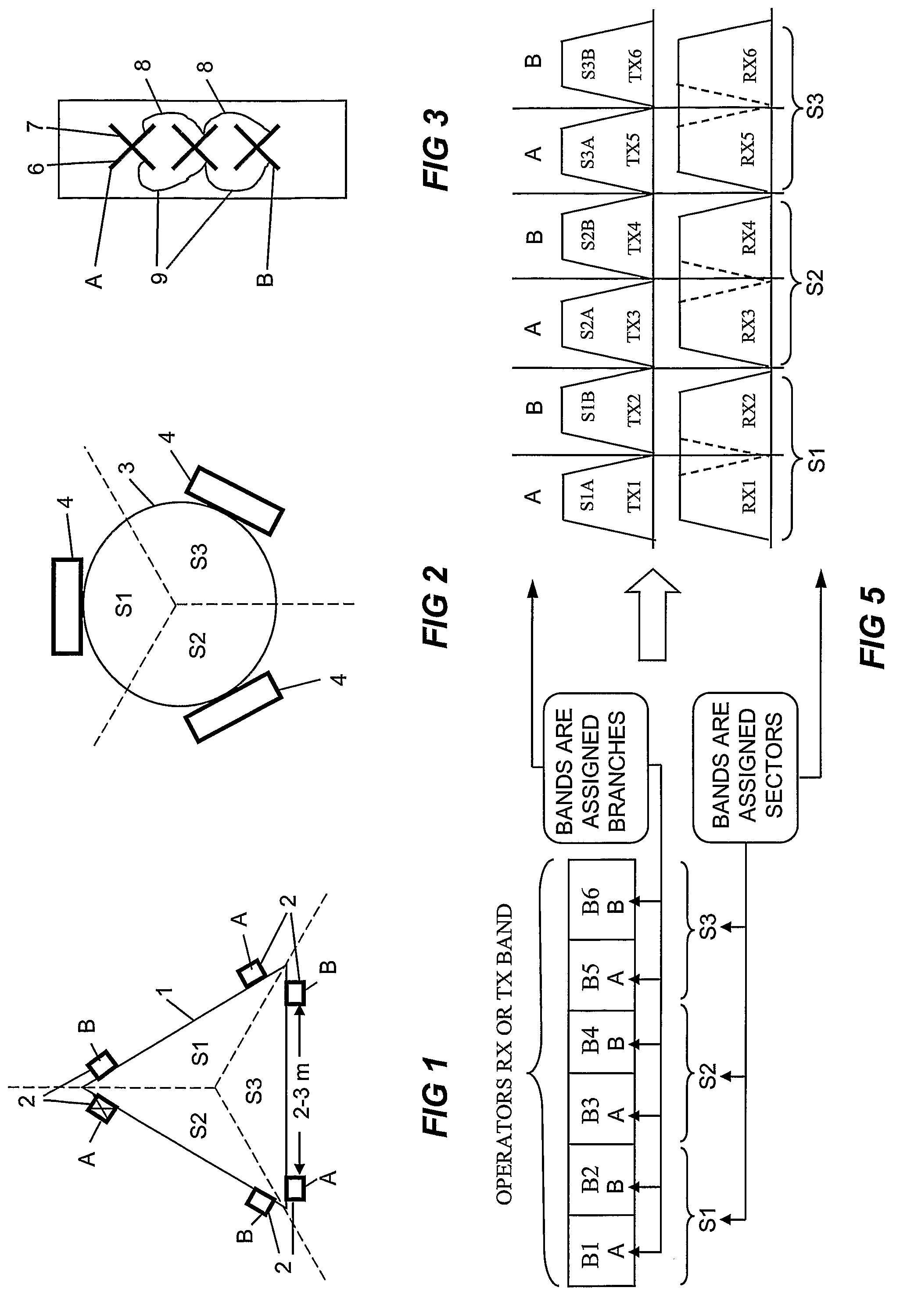
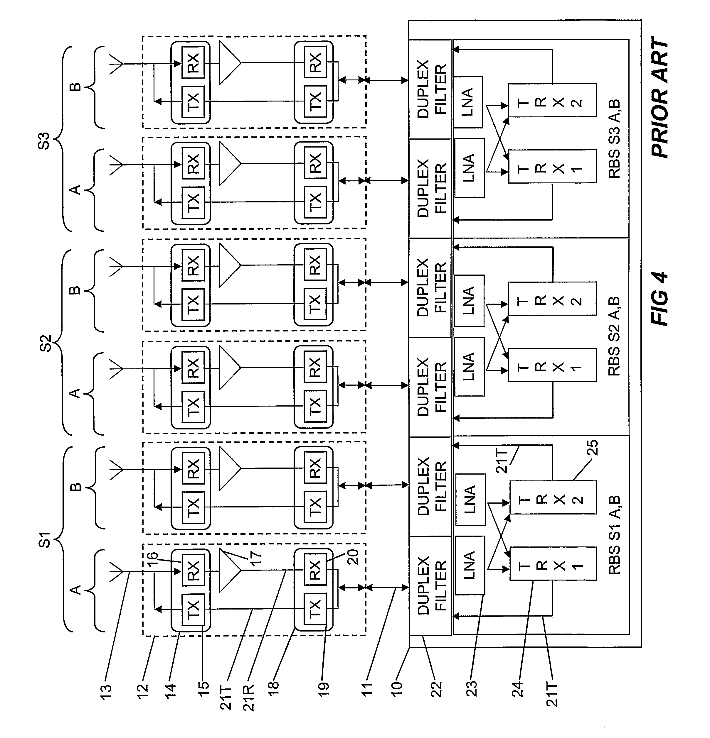
[0050]In FIG. 6 a radio base station site in accordance with the invention is shown wherein the just discussed assignment procedure has been implemented. It should be understood that used legends, such as S1-S3, TX1-TX6, RX1-6, and A, B refer to the same objects discussed above in connection with FIG. 5. In FIG. 6 the notation, for example, S3A means sector S3 branch A. The site comprises two TMAs 26, 27, two feeders 11, two filter units 28, 29 and a RBS 10. The site be described as a 3 sector site with 2 feeders. TMA 26 comprises the A branch of the antenna arrangement and TMA 27 comprises the B branch. TMA 26 is connected to a single feeder 11 which in its turn is connected to the filter unit 28. TMA 27 is connected to a single feeder 11 which in its turn is connected to the filter unit 29 provided in or outside the RBS 10. Filter unit 28 comprises three band pass filters TX1, TX3 and TX5 and a full band RX filter arranged in the manner shown. Filter unit 29 comprises three band p...
second embodiment
[0065]The second embodiment comprises two TMAs 35 and 36. TMA 35 has a construction of the same general kind as TMA 26 in FIG. 6 in that it comprises a plurality of diplexed TX filters connected to a rail 31 and a plurality of full band RX filters connected to a combiner via a respective RF amplifier and narrow combined RX filters. The differences over FIG. 6 are that each sector has an additional TX filter for the additional RBS station and that the combined RX filters in each sector shall pass the RX signals of the additional RBS station. The filters in each of the sectors of branch A are indicated in FIG. 8 and in branch A they are connected in the manner shown in TMA 35. The filters in each of the sectors of branch B are indicated at an reduced scale in FIG. 10 and are connected in a similar manner shown in TMA 36 in which there is no room for reference designations. In each TMA the TX signals are splitted.
[0066]Two separate filters TX1 and TX3 in TMA 35 may be replaced with a s...
third embodiment
[0074]With this third embodiment synth hopping may take place within each assigned TX band and also between the TX bands of an individual sector; the latter frequency hopping is referred to as base band hopping. It is obvious that base band hopping in sector S1 can take place between TX1 and TX3. Less obvious is that it can also take place in the same sector S1 in the other branch B. This is so because a mobile within this sector is reachable from branch A as well as from branch B. In particular base band hopping in sector S1 may take place between TX1, TX3, TX2 and TX4. In sector S2 base band hopping may take place between TX5, TX7, TX6 and TX8. In sector S3 it may take place between TX9, TX11, TX 10 and TX12.
[0075]The means by which synth hopping and base band hopping are realized in sector S1 are shown in the schematic block diagram in FIG. 14. A synth hopper for each base band is shown at 49 and a base band hopper is shown at 50. Synth hopping and base band hopping takes place a...
PUM
 Abstract
Description
Claims
Application Information
 - R&D
- Intellectual Property
- Life Sciences
- Materials
- Tech Scout
- Unparalleled Data Quality
- Higher Quality Content
- 60% Fewer Hallucinations
Browse by: Latest US Patents, China's latest patents, Technical Efficacy Thesaurus, Application Domain, Technology Topic, Popular Technical Reports.
© 2025 PatSnap. All rights reserved.Legal|Privacy policy|Modern Slavery Act Transparency Statement|Sitemap|About US| Contact US: help@patsnap.com


