Optical hair removing device

a hair removal device and optical technology, applied in the field of optical hair removal devices, can solve the problems of difficult to confirm whether the irradiation unit makes a firm contact with the skin, and the actual movement distance of the light irradiation unit on the skin is difficult to detect, so as to reduce the burden on the skin, accurate detect the actual movement, and effectively remove the hair

Inactive Publication Date: 2008-05-22
MATSUSHITA ELECTRIC WORKS LTD
View PDF5 Cites 37 Cited by
  • Summary
  • Abstract
  • Description
  • Claims
  • Application Information

AI Technical Summary

Benefits of technology

[0012]In the embodiment of the present invention, the movement detection unit directly and accurately detects an actual movement of the irradiation unit on the skin. Therefore, it is possible to prevent light from being irradiated on the same spot of the skin multiple times, which reduces burden to the skin. Further, the contact detection unit accurately detects the contact between the irradiation unit and the skin. Accordingly, even when light having low irradiation energy is used, the hair can be effectively removed. Also, it is possible to avoid that light is let out through a gap between the irradiation unit and the skin.
[0013]The movement detection unit is a roller encoder, and the contact detection unit includes contact switches. Therefore, the movement of the irradiation unit on the skin or the contact between the irradiation unit and the skin can be detected with a simple configuration.
[0014]By providing the light detection unit

Problems solved by technology

Since, however, the moving mechanism moves the irradiation unit within the specific range under the control of the control unit in the optical hair removing device described in the patent application supra, it was difficult to detect the actual moving distance of the light irradiating unit on

Method used


Image

  • Optical hair removing device
  • Optical hair removing device
  • Optical hair removing device

Examples


Embodiment Construction

[0021]Embodiments of the present invention will now be described in detail with reference to the accompanying drawings which form a part hereof.

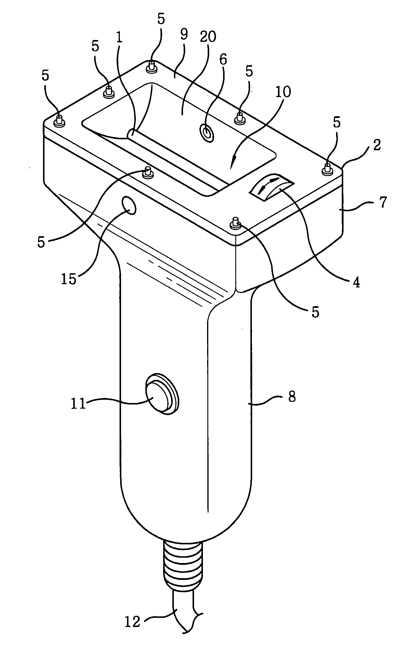
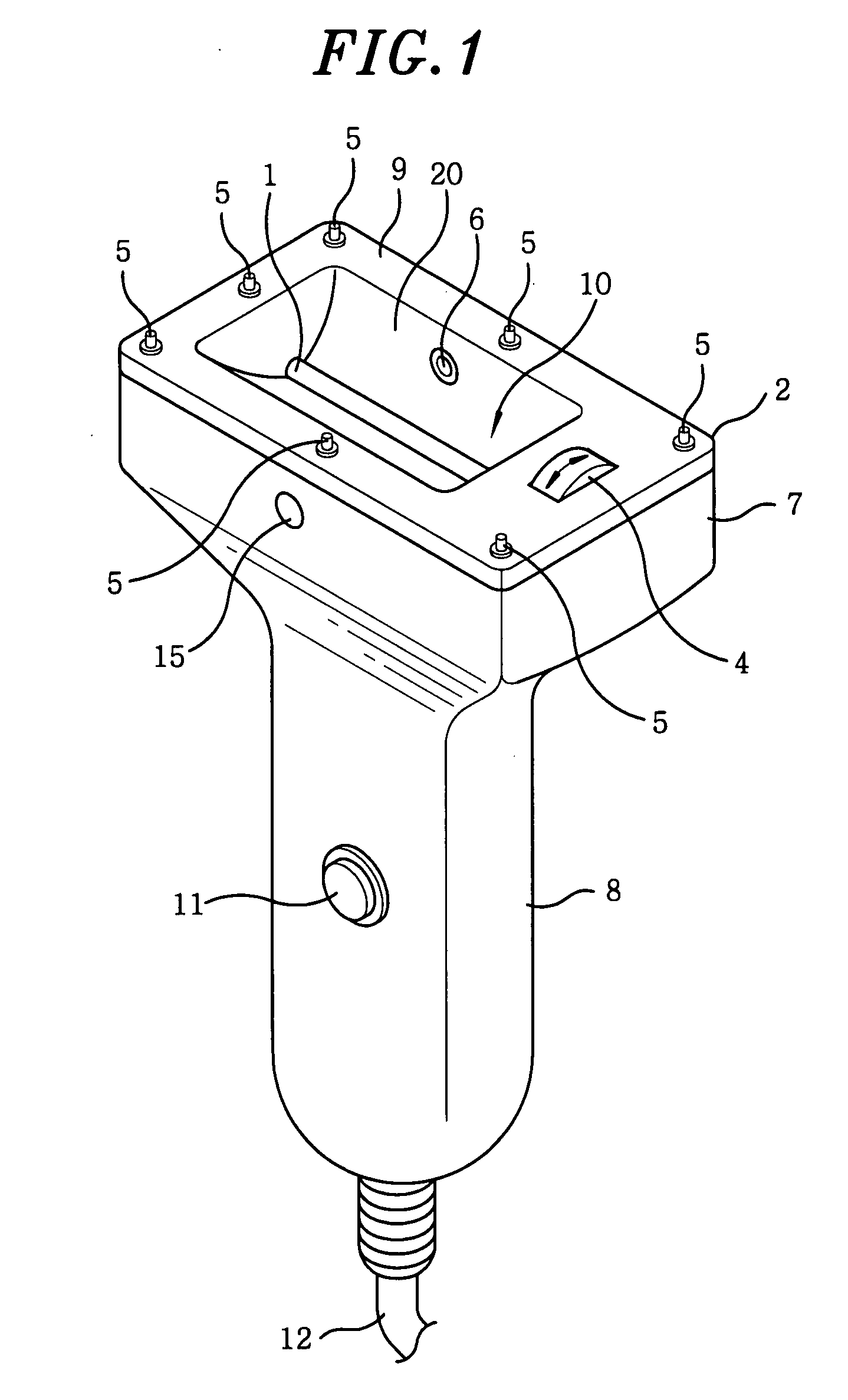
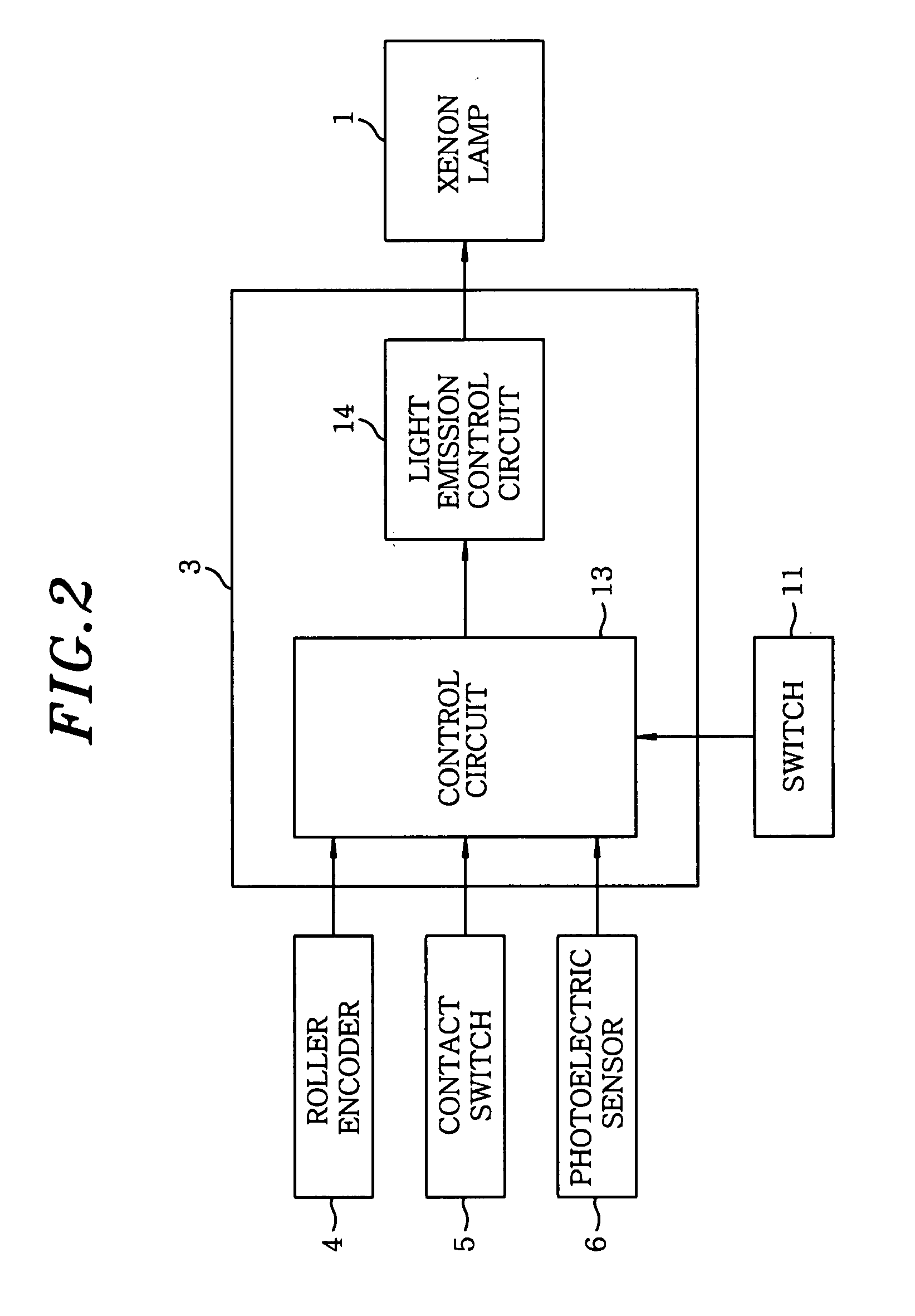
[0022]FIGS. 1 and 2 illustrate an optical hair removing device in accordance with an embodiment of the present invention. As shown in FIGS. 1 and 2, the optical hair removing device includes a light emitting unit 1, e.g., a Xenon lamp or the like, for emitting a light; an irradiation unit 2 for irradiating the light emitted from the Xenon lamp 1 to body hairs on a skin; a control unit 3 for controlling the light emission of the Xenon lamp 1. The irradiation unit 2 has a movement detection unit 4, e.g., roller encoder or the like, for detecting a movement of the irradiation unit 2 on the skin; and contact switches 5 serving as a contact detection unit for detecting a contact between the irradiation unit 2 and the skin.

[0023]Installed in the irradiation unit 2 is a light detection unit 6, e.g., photoelectric sensor or the like, for detecting t...


PUM


Abstract

An optical hair removing device includes a light emitting unit for emitting a light and an irradiation unit for irradiating the light emitted from the light emitting unit to body hairs on a skin. Further, the optical hair removing device includes a control unit for controlling the light emission unit. The irradiation unit has a movement detection unit for detecting a movement of the irradiation unit on a skin and a contact detection unit for detecting a contact between the irradiation unit and the skin.

Description

FIELD OF THE INVENTION[0001]The present invention relates to an optical hair removing device for removing body hairs on a skin by irradiating a light thereon.BACKGROUND OF THE INVENTION[0002]A conventional optical hair removing device includes a laser source for emitting a laser beam, an irradiation unit for irradiating the laser beam emitted from the laser source to body hairs on a skin, a moving mechanism for moving the irradiation unit along the contour of the skin in X and Y directions, and a control unit for controlling the moving mechanism.[0003]The body hair is automatically removed by moving the irradiation unit on the skin in X or Y direction within a specific range with the use of the moving mechanism controlled by the control unit (see, e.g., Japanese Patent Laid-open Application No. 2002-172179).[0004]Since, however, the moving mechanism moves the irradiation unit within the specific range under the control of the control unit in the optical hair removing device describe...

Claims


Application Information

Patent Timeline
IPC IPC(8): A61B18/18
CPCA45D26/00A45D26/0009A61B18/203A61B2017/00026A61B2019/409A61B2018/00476A61B2018/1807A61B2019/465A61B2018/00452A61B2090/049A61B2090/065A61N5/06
Inventor OKAWA, KAZUMI
Owner MATSUSHITA ELECTRIC WORKS LTD
Why Eureka
Try Eureka