Locking bone plate with bushing anti-rotation feature

a bushing and bone plate technology, applied in the field of improved bone plates, can solve the problems of difficult handling of bushings, difficult engagement of the internal thread of the bushing with the thread of the screw head, and complicating surgical procedures, and achieves the effect of simple production

Inactive Publication Date: 2008-05-22
TORNIER SA SAINT ISMIER
View PDF38 Cites 89 Cited by
  • Summary
  • Abstract
  • Description
  • Claims
  • Application Information

AI Technical Summary

Benefits of technology

[0009] The present invention is directed to an improved bone plate with an expandable bushing, in which the rotation o

Problems solved by technology

In use, such bushings are difficult to handle: when the head is screwed into the bushing, it is difficult for the internal thread of the bushing to engage with the thread of the screw head since the bushing tends to turn round on itself in the hole in the plate due to the fact that the connection between the bushing and the wall of the hole is still movable.
A surgeon thus has difficulties in effectively screwing the head of the screw into the bushing and this complicates surgical procedures and increases intervention time.
In practice, forming a rotation-blocking enl

Method used


Image

  • Locking bone plate with bushing anti-rotation feature
  • Locking bone plate with bushing anti-rotation feature
  • Locking bone plate with bushing anti-rotation feature

Examples


Embodiment Construction

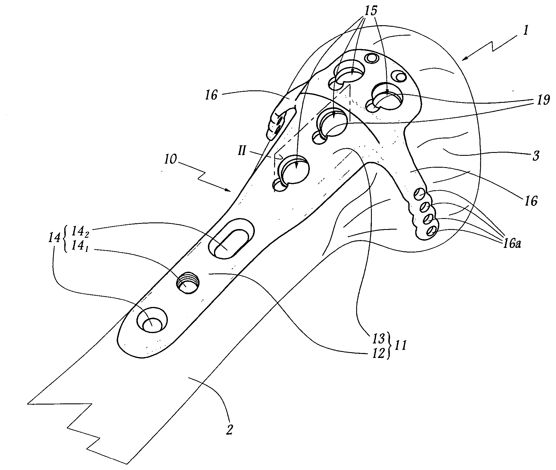
[0025] In FIG. 1, the upper end portion of a humerus is schematically shown, the diaphysis and the epiphysis of which are referenced with the numerals 2 and 3 respectively. For the sake of convenience the following description will refer to the humerus in its anatomical position for a patient standing erect, in such a way that the terms “upper” and “high” designate an upwards direction in FIGS. 1 to 3, while the terms “lower” and “low” designate the opposite direction.

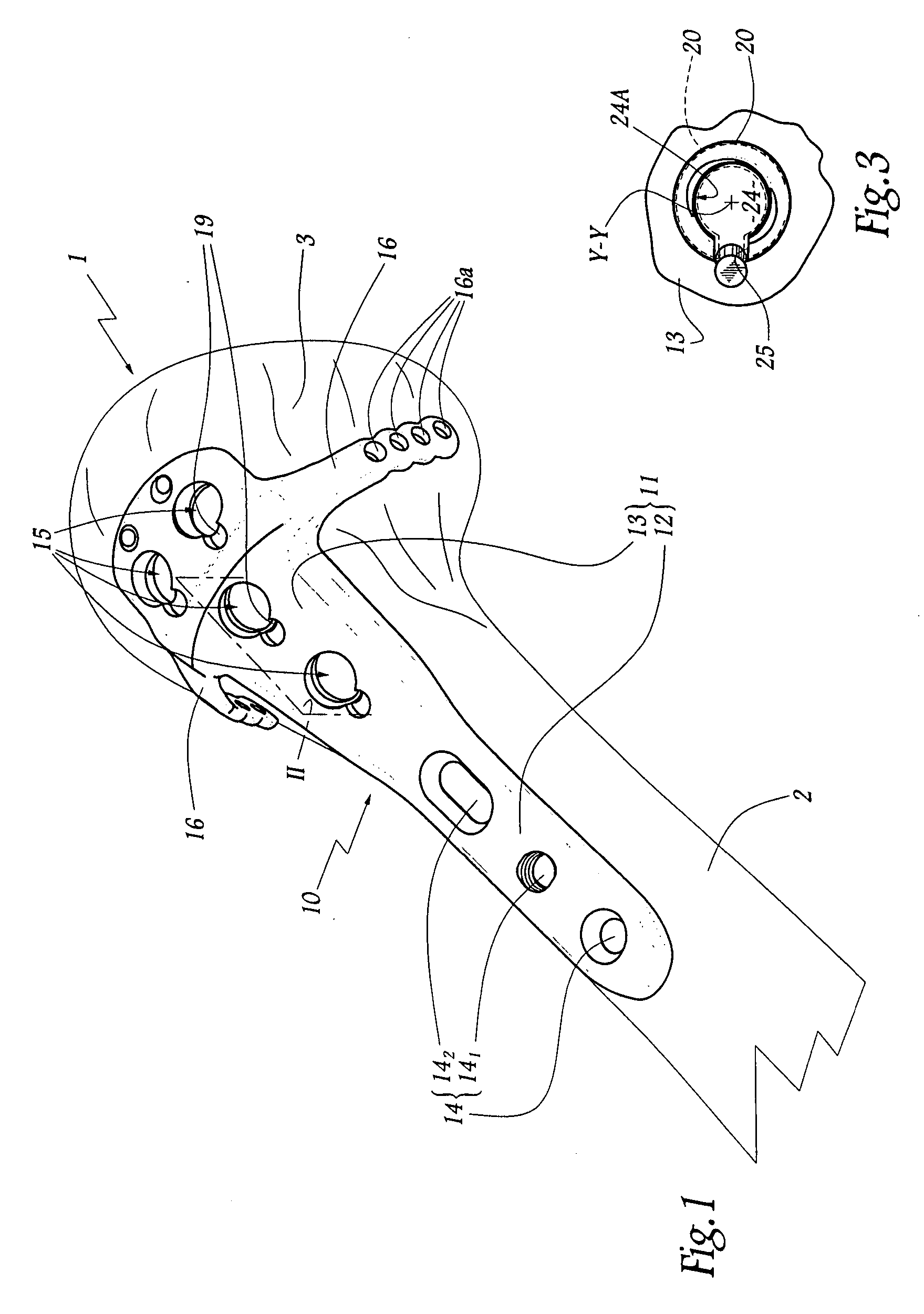
[0026] On the humerus 1 is fitted a humeral plate 10 comprising a main elongate body 11 extending in the longitudinal direction of the humerus, both at the diaphysis 2 thereof and at the epiphysis 3 thereof. The body 11 thus includes a diaphyseal portion 12 and an epiphyseal portion 13 located at the diaphysis and the epiphysis respectively of the humerus.

[0027] A plurality of holes 14 pass through the thickness of the portion 12 and open onto the humeral diaphysis 2, including a threaded hole 141 and a hole 142 with...


PUM


Abstract

A locking plate intended to be implanted at a bone site and a method for producing and implanting this device. At least one expandable bushing is engaged with a through-hole in the plate. The bushing includes an exterior surface with at least one recess and a passageway including a threaded interior surface. The expandable bushing is initially in a first configuration that permits poly-axial rotation of the bushing within the through-hole. An elongated anchoring member is provided with a distal portion and a proximal portion including a head portion with threads complementary to the threads on the interior surface of the expandable bushing. The proximal portion expands the bushing to form a friction lock between the bushing and the plate in a selected polyaxial position in a second configuration. At least one discrete blocking member is fixedly engaged with the body portion of the plate and extends into the through-hole to engage with the recess on the expandable bushing. The blocking member inhibiting rotation of the expandable bushing relative to the through-hole.

Description

[0001] This application claims priority to French application no. 0610141, titled DISPOSITIF PROTHETIQUE OU D'OSTEOSYNTHESE A OLIVE FENDUE, filed on Nov. 20, 2006. FIELD OF THE INVENTION [0002] The present invention is directed to an improved bone plate with an expandable bushing, in which the rotation of the bushing about its main axis is blocked before expansion, and to a method of making and implanting such a device. BACKGROUND OF THE INVENTION [0003] Bone plates allow fractures of the anatomical neck of the humerus or of the end of the humerus situated nearer the elbow and also fractures of the upper end of the tibia, or even other epiphyseal lesions of long bones to be minimised. [0004] WO-A-2003 / 007832 discloses a plate that is fixed to the bone by screws which each comprise, on the one hand, a threaded rod for anchoring to the bone, inserted through a through-hole in the plate, and, on the other hand, a threaded head for immobilising the screw relative to the plate, screwed i...

Claims


Application Information

Patent Timeline
IPC IPC(8): A61B17/58A61B17/56
CPCA61B17/8042A61B17/8061A61B17/8047
Inventor MANCEAU, THIERRY
Owner TORNIER SA SAINT ISMIER
Why Eureka
Try Eureka