Rivet Setting Method and System

a technology of setting method and setting system, which is applied in the direction of metal-working apparatus, metal-working apparatus, manufacturing tools, etc., can solve the problems of not being able to apply clamping force and not being able to prove the effect of correct practice, and achieve the effect of significantly reducing the amount of adhesive and changing the clamping for

Inactive Publication Date: 2008-05-29
BAYERISCHE MOTOREN WERKE AG
View PDF2 Cites 5 Cited by
  • Summary
  • Abstract
  • Description
  • Claims
  • Application Information

AI Technical Summary

Benefits of technology

[0008]The present invention provides a method for setting punch rivets, in which a reduction of the joining forces is possible while maintaining the known punch riveters.
[0010]In contrast to the prior art, a clamping device which presses together the sheets to be joined is no longer used, but rather the sheets are pressed together before the actual setting procedure via the punch and the punch rivet itself. The clamping device, which is still present, is only still used for guiding the rivet during the supply of the punch rivet to the surface of the components to be connected by the punch. However, it may no longer apply clamping force, because it no longer touches the components to be connected. Surprisingly, it has been shown that the clamping force to be applied via the rivet is less than previously used and the setting force, i.e., the force with which the punch rivet is driven into the sheets / components, may also be significantly reduced. Therefore, less tool wear arises because of the lower joining forces, and the punch rivet clamp itself may also be minimized in regard to weight and thus material costs. Therefore, even robots having a small carrying force may be used. A further advantage may be seen in that the punch riveters used up to this point may be maintained without structural changes. Only the controller of the clamping device must be altered, so that it is ensured that the clamping device no longer touches the components to be connected.
[0012]It is also known to simultaneously glue the components to be connected using punch rivets, in that adhesive is applied in spots or strips on the two interior sides of the sheets / components to be connected before the punch rivet is set. To distribute the adhesive on the sheet surfaces before the punch riveting, either longer waiting times are set at constant clamping force, or alternatively, the level of the clamping force may be changed. An advantage of this embodiment is that the air channels otherwise occurring in the adhesive distributed between the sheets when using a clamping device for clamping and thus distributing the adhesive may be significantly reduced.

Problems solved by technology

With clamping forces at a level of this type according to the US patent, a deep-drawing procedure is to be avoided in the sheets in the area of the punch rivet, which has not proven to be correct in practice, however.
However, it may no longer apply clamping force, because it no longer touches the components to be connected.

Method used


Image

  • Rivet Setting Method and System
  • Rivet Setting Method and System

Examples


example 2

[0029]

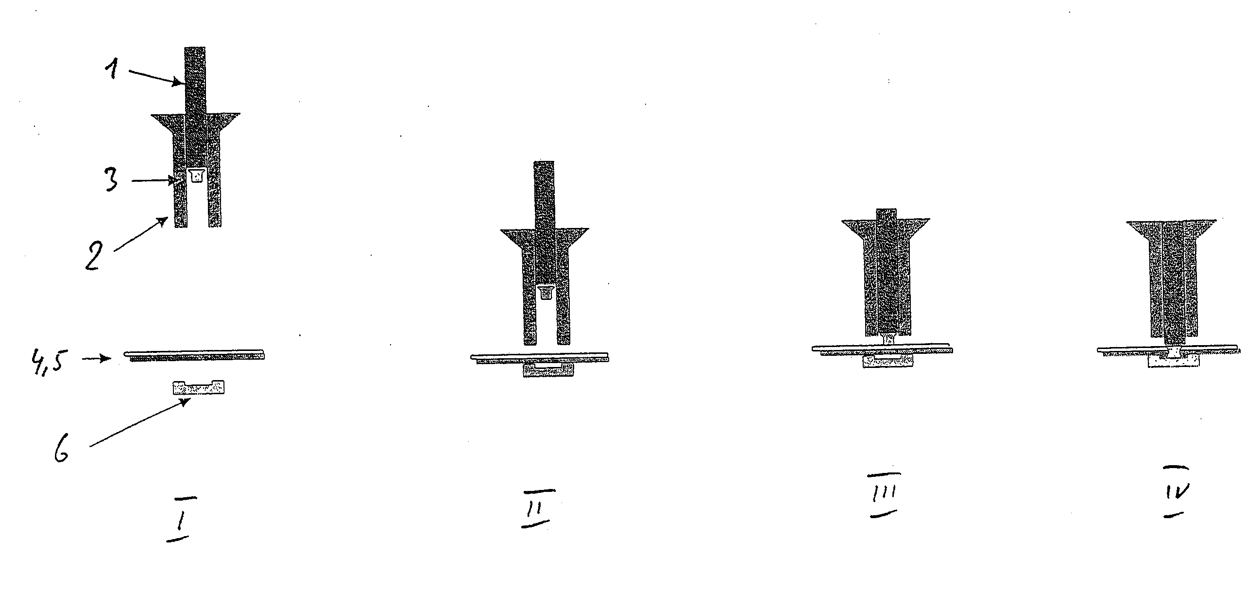
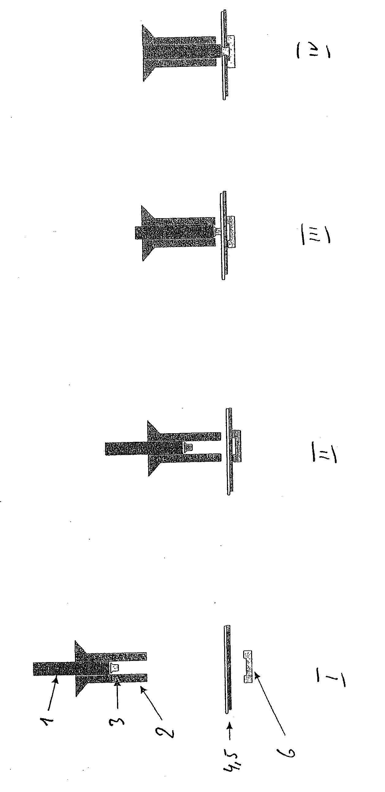
upper sheet material:ZSTE 420 BH (steel),sheet thickness: 1.0 mm,lower sheet material:EN AW 5454 (aluminum),sheet thickness: 1.2 mm,adhesive between the sheets:Betamate 1496,semitubular punch rivet made of steel,C geometry, 5.3 × 5 mm, hardness 4Punch rivet method:prior art:present invention:clamping force via clampingclamping force via punch rivet:device:6 kN,6 kN,setting force: 50 kNsetting force: 40 kN

[0030]As these two examples show, the setting force may be reduced by over 20% according to the present invention. Therefore, lighter punch riveters may be used for the same application.

[0031]It has also been demonstrated that in the method according to the present invention, the adhesive is distributed significantly more uniformly between the sheets. The air channels in the adhesive layer observed up to this point in the prior art are significantly reduced and / or no longer occur.


PUM

PropertyMeasurementUnit
timeaaaaaaaaaa
clamping forceaaaaaaaaaa
clamping forcesaaaaaaaaaa

Abstract

A method is provided for self-pierce riveting which reduces a setting force required for setting the rivets. For this purpose, a clamping force produced by a clamping device is substituted by the force produced by a rivet on a punch. The clamping force varies within a known magnitude, whereas the setting force is reduced by 20%.

Description

CROSS-REFERENCE TO RELATED APPLICATIONS[0001]This application is a continuation of PCT International Application No; PCT / EP2006 / 007349, filed on Jul. 26, 2006, which claims priority under 35 U.S.C. §119 to German Application No. 10 2005 037 914.1, filed Aug. 10, 2005, the entire disclosures of which are expressly incorporated by reference herein.BACKGROUND AND SUMMARY OF THE INVENTION[0002]The present invention relates to a method for self-pierce riveting, in particular using semitubular punch rivets to connect at least two components, in particular two sheets, with the aid of a self-pierce riveter having a punch. The punch rivet to be set is pressed by the punch through the sheets to be connected.[0003]Self-pierce or punch riveting has been known for many years, including in automobile manufacturing technology. Typically, aluminum sheets are connected with the aid of semitubular rivets at an overlap joint.[0004]Punch riveting is understood as a riveting method in accordance with DI...

Claims


Application Information

Patent Timeline
Patent Type & Authority Applications(United States)
IPC IPC(8): B23P11/00
CPCB21J15/025Y10T29/49956Y10T29/49908Y10T29/49943Y10T29/49835Y10T29/49915
Inventor BERNDL, JUERGENREINSTETTEL, MARC
Owner BAYERISCHE MOTOREN WERKE AG
Why Eureka
Try Eureka