
Band Saw Blade and Cutting Method

a band saw blade and cutting method technology, applied in the field of band saw blades, can solve the problems of shortening the service life increasing the cutting noise, and degrading the work environment, so as to reduce the cutting length reduce the cutting resistance of the workpiece, and suppress the cutting course deviation of the band saw blade.

Active Publication Date: 2008-05-29
AMADA CO LTD
View PDF20 Cites 47 Cited by
  • Summary
  • Abstract
  • Description
  • Claims
  • Application Information

AI Technical Summary

Benefits of technology

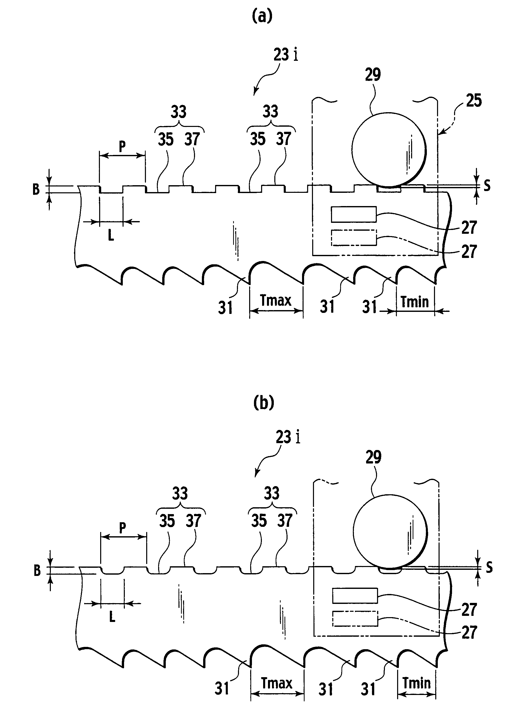
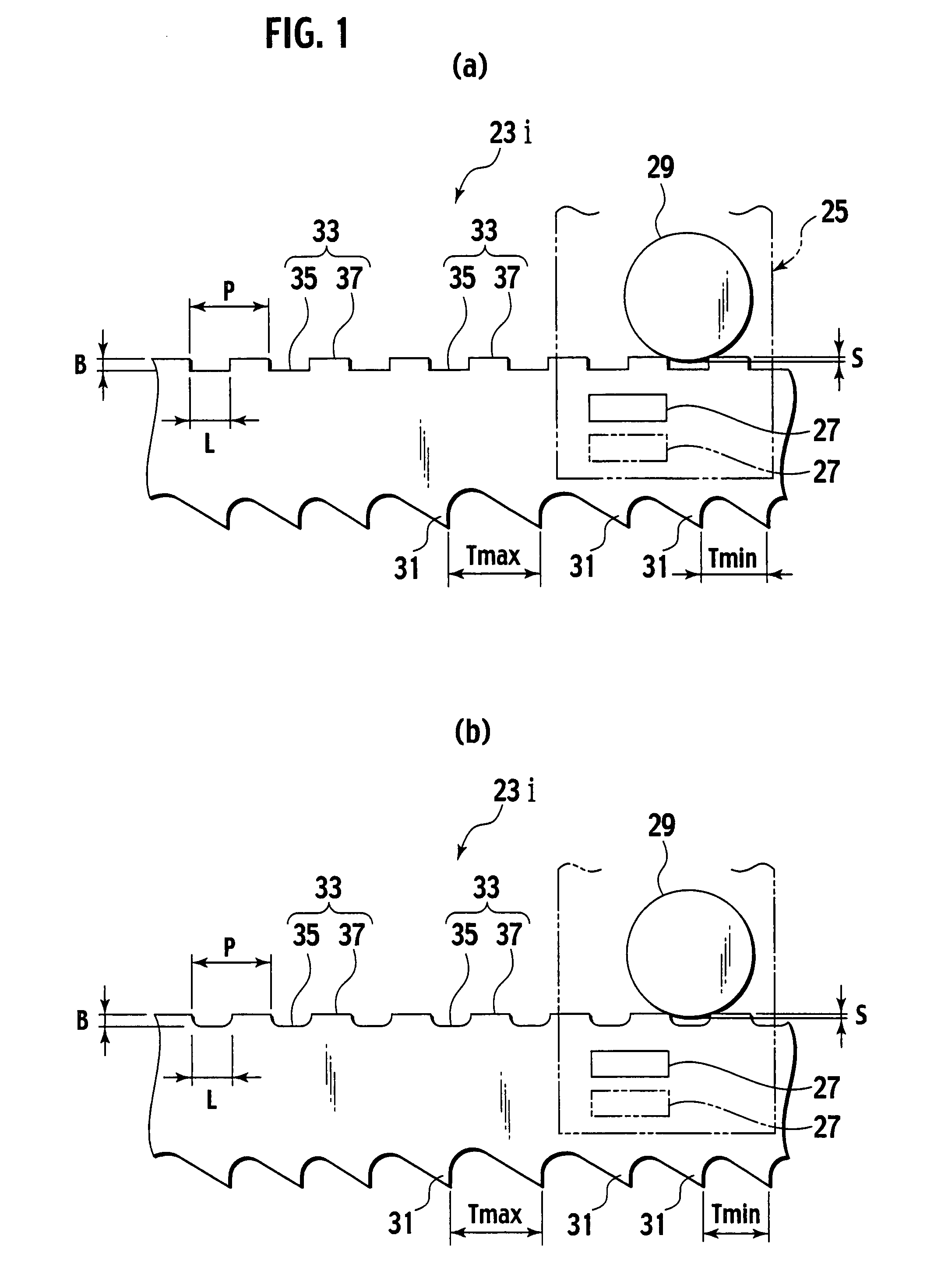
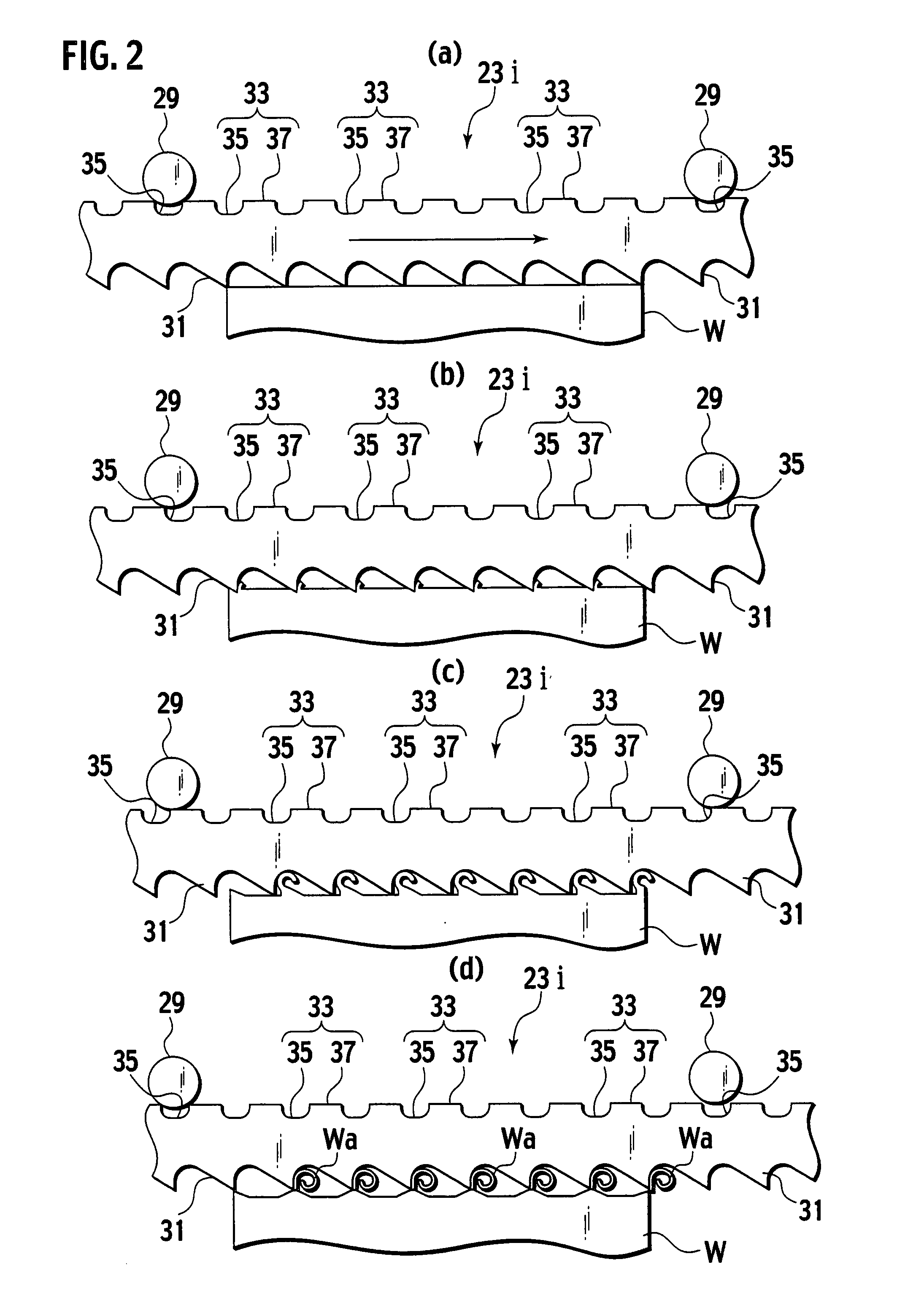
[0013]Besides the general cutting function, the band saw blade is configured so that the many concave and convex portions are consecutively formed on the rear of the band saw blade, and so that the length of each concave and convex portions is equal to or smaller than the fourfold of the maximum pitch of the tooth top of the tooth. Due to this, by continuously engaging and disengaging the concave portions of the many concave and convex portions with and from the backup guide during cutting of the workpiece, the band saw blade can be forcedly vibrated in a band width direction in the cutting region. This enables alternately performing an operation for causing the teeth to bite into the workpiece and an operation for causing the teeth to scrape away chips at short intervals.
[0029]As stated so far, according to the present invention, the operation for causing the teeth to bite into the workpiece and the operation for causing the teeth to scrape away the chips can be alternately performed at short intervals in the cutting region. It is, therefore, possible to reduce the cutting length of the band saw blade and reduce the cutting resistance of the workpiece irrespectively of a magnitude of the workpiece. Due to this, the cutting course deviation of the band saw blade is suppressed, the service life of the band saw blade is prolonged, the cutting noise is abated, and the work environment is improved.

Problems solved by technology

Due to this, the band saw blade causes a cutting course deviation, which disadvantageously shortens a service life of the band saw blade, increases the cutting noise, and degrades the work environment.

Method used


Image

  • Band Saw Blade and Cutting Method
  • Band Saw Blade and Cutting Method
  • Band Saw Blade and Cutting Method

Examples


Embodiment Construction

[0052]An embodiment of the present invention will be described below with reference to the drawings. A general configuration of a horizontal band saw machine according to an embodiment will be described first with reference to FIG. 19. FIG. 19 is a front view of the horizontal band saw machine according to the embodiment. In the following description, “horizontal” and “vertical” mean right and left and upward and downward, respectively relative to a direction of the drawings at the time of publication in a patent gazette.

[0053]As shown in FIG. 19, a horizontal band saw machine 1 according to the embodiment includes a box-type support frame 3, and a table 5 supporting a workpiece W is provided on the support frame 3. Furthermore, a fixed vice 7 and a movable vice 9, between which the workpiece W is held, are provided on the support frame 3 to be opposed to each other, and the movable vice 9 is movable in a horizontal direction in which the movable vice 9 is closer to or farther from ...


PUM

PropertyMeasurementUnit
Lengthaaaaaaaaaa
Lengthaaaaaaaaaa
Frequencyaaaaaaaaaa

Abstract

Concave / convex portions are consecutively formed on a back of a band saw blade. The concave / convex portions include concave portions engageable with and disengageable from a backup guide of a band saw guide unit, and convex portions adjacent to the concave portions. A length of each of the concave / convex portions is configured to be equal to or smaller than four times a maximum pitch of a tooth top of each tooth.

Description

TECHNICAL FIELD[0001]The present invention relates to a band saw blade having many teeth and a cutting method for cutting a workpiece in a cutting region.BACKGROUND ART[0002]Conventionally, in general, a band saw machine is often used when a metal or wood workpiece is to be cut and the band saw machine includes a band saw blade as a cutting tool. The band saw blade includes many teeth including many unset teeth, many right set teeth set rightward, and many left set teeth set leftward.[0003]Moreover, various contrivances have been employed, e.g., changes in a height difference among the teeth, amounts of set of the right set teeth and the left set teeth, and tooth top pitches have been designed so as to improve cutting performance (cuttability) with respect to a workpiece, or to reduce noise generated at the time of cutting a workpiece (cutting noise).[0004]As a conventional technique relating to the present invention, Japanese Patent Brochure No. 2953767 is known.[0005]Meanwhile, if...

Claims


Application Information

Patent Timeline
IPC IPC(8): B23D57/00B26D7/08
CPCB23D55/082B23D61/123B23D55/088Y10T83/0405Y10T83/04Y10T83/935Y10T83/9319
Inventor HASHIMOTO, TOSHIYUKINAGANO, YUJITSUJIMOTO, SUSUMU
Owner AMADA CO LTD
Learn More