
Heat-dissipation device with dust-disposal function

a technology of heat dissipation device and dust dissipation function, which is applied in the direction of cleaning heat dissipation device, tubular element, lighting and heating apparatus, etc., can solve the problems of significantly reducing and the accumulation of dust in the air between the metallic fins of the cooling fin, so as to improve the heat dissipation capability of the heat dissipation devi

Inactive Publication Date: 2008-05-29
INVENTEC CORP
View PDF10 Cites 22 Cited by
  • Summary
  • Abstract
  • Description
  • Claims
  • Application Information

AI Technical Summary

Benefits of technology

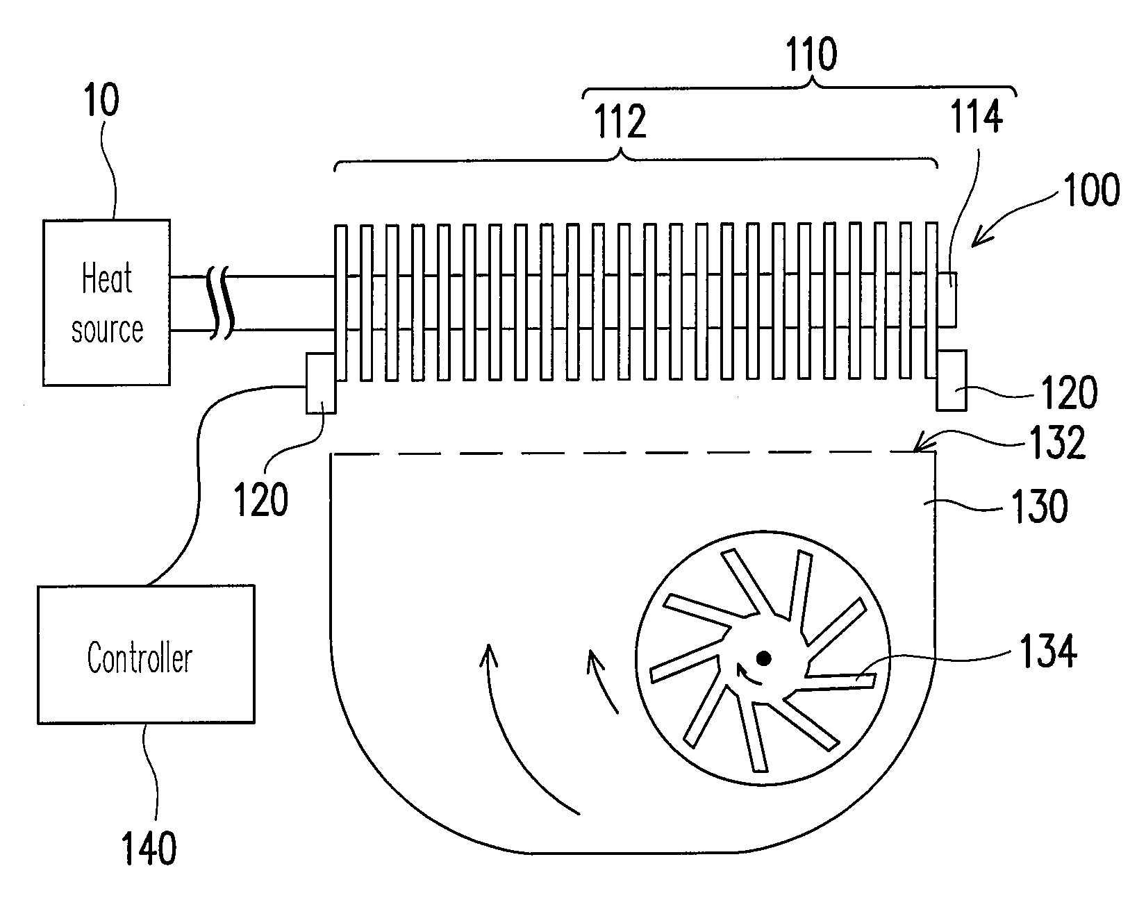
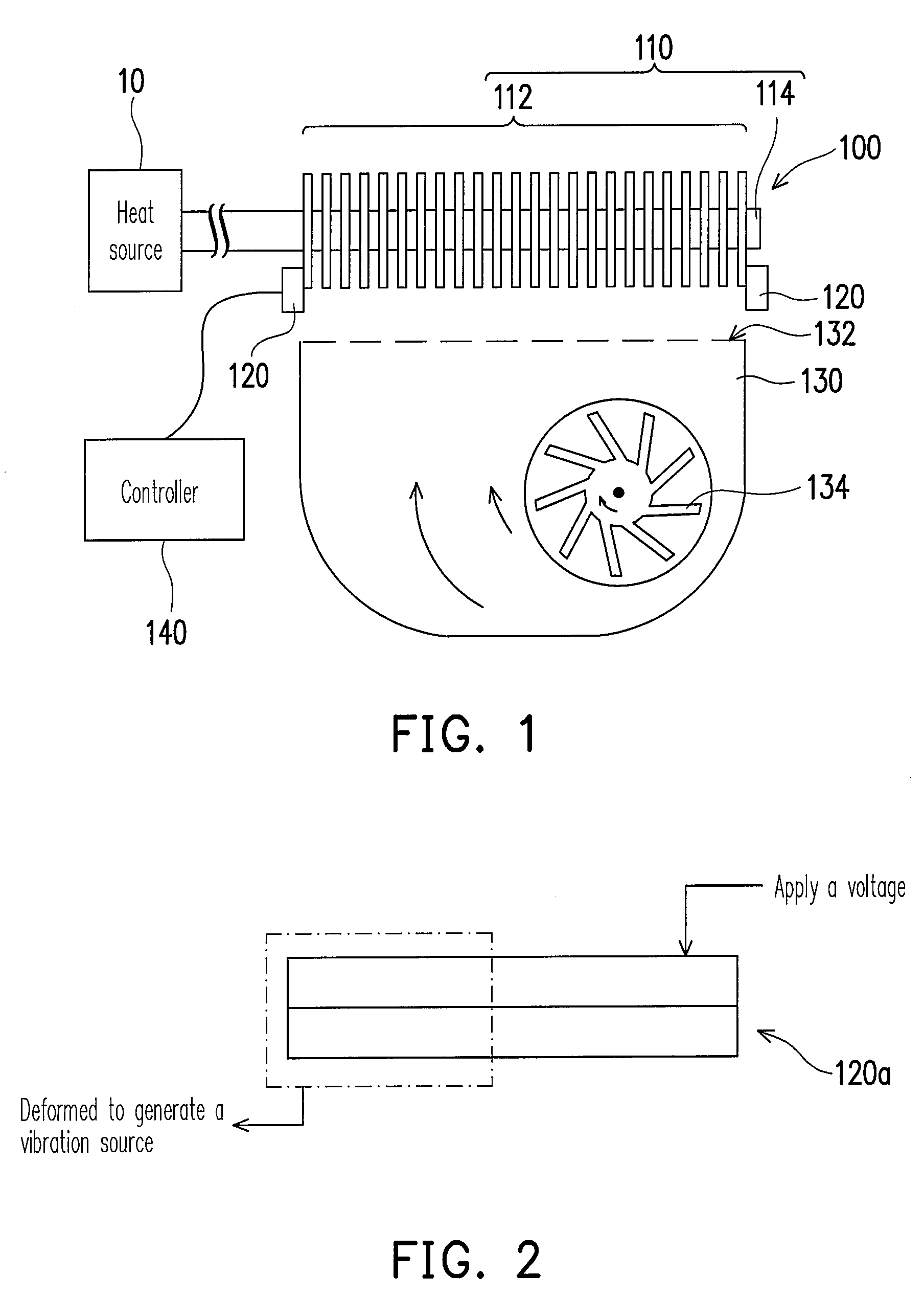
[0016]The present invention adopts the heat-dissipation device with dust-disposal function, and thus the dust on the metallic fins is shook off by vibration of the vibrator. Since the heat-dissipation device can automatically clean the dust on the metallic fins periodically or nonperiodically, the airflow generated by the fan can quickly remove the waste heat from the metallic fins, thereby significantly improving the heat-dissipation capability of the heat-dissipation device.

Problems solved by technology

It should be noted that after the heat-dissipation device is used for a long time, dust in the air is gradually accumulated between the metallic fins of the cooling fins.
If not being cleaned, excessive dust accumulated on the metallic fins may result in that the airflow blown by the fan cannot remove the waste heat from the cooling fins easily, thereby significantly reducing the heat-dissipation capability of the heat-dissipation device.

Method used


Image

  • Heat-dissipation device with dust-disposal function
  • Heat-dissipation device with dust-disposal function
  • Heat-dissipation device with dust-disposal function

Examples


Embodiment Construction

[0022]Referring to FIG. 1, a schematic view of a heat-dissipation device with dust-disposal function according to an embodiment of the present invention is shown. The heat-dissipation device 100 mainly includes a heat-conducting module 110 and at least one vibrator 120, and the heat-conducting module 110 is used to dissipate heat of electronic devices with high heat-generating rate, so as to reduce the operating temperature of the electronic devices in a system. The heat-conducting module 110 is generally made of metallic material with high heat conductivity such as Cu and Al, and is disposed on the electronic devices and connected to an air-cooling heat-dissipation module or water-cooling heat-dissipation module in the system, so as to achieve the purpose of heat dissipation.

[0023]In this embodiment, the heat-conducting module 110 includes a plurality of metallic fins 112 arranged in parallel, and the metallic fins 112 in regular arrangement are stacked with a gap existing therebet...


PUM


Abstract

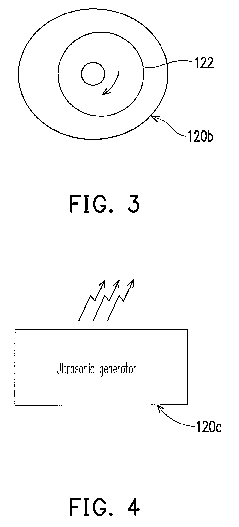
A heat-dissipation device with dust-disposal function for removing dust from cooling metallic fins is provided, which includes a heat-conducting module and a vibrator. The heat-conducting module has a plurality of metallic fins, and the vibrator is directly or indirectly connected to the heat-conducting module to provide a vibrating source for the metallic fins, such that the dust accumulated on the metallic fins is shook off by vibration. The vibrator may be a piezoelectricity element or an eccentric motor. In addition, the vibrator may be an ultrasonic generator disposed near the heat-conducting module to provide a non-contact vibrating source for the metallic fins.

Description

CROSS-REFERENCE TO RELATED APPLICATION[0001]This application claims the priority benefit of Taiwan application serial no. 95143313, filed Nov. 23, 2006. All disclosure of the Taiwan application is incorporated herein by reference.BACKGROUND OF THE INVENTION[0002]1. Field of the Invention[0003]The present invention relates to a heat-dissipation device, and more particularly to a heat-dissipation device with dust-disposal function.[0004]2. Description of Related Art[0005]Recently, with the rapid progress of computer science and technology, the operation speed of the computer is improved increasingly, and the heat-generating rate of electronic devices in the computer host is increased accordingly. In order to prevent overheat of the electronic devices in the computer host, which may result in temporary or permanent failure of electronic devices, a sufficient heat-dissipation performance must be provided for the electronic devices in the computer.[0006]Generally speaking, a heat-dissipa...

Claims


Application Information

Patent Timeline
IPC IPC(8): F28G7/00
CPCF28D2021/0031F28G7/00F28F1/24
Inventor WANG, FRANKYANG, CHIH-KAI
Owner INVENTEC CORP
Learn More