Stabilized Dc Power Supply Credit

a dc power supply and circuit technology, applied in the direction of electric variable regulation, process and machine control, instruments, etc., can solve the problems of negative feedback instability, oscillation, and no prior technology cited in the above-mentioned references solves this essential problem, and achieves high stability of dc, without sacrificing stability, and fast response speed

Inactive Publication Date: 2008-05-29
NANOPOWER SOLUTION
View PDF10 Cites 2 Cited by
  • Summary
  • Abstract
  • Description
  • Claims
  • Application Information

AI Technical Summary

Benefits of technology

[0042]By means of the present invention, a hysteresis function or a pseudo-hysteresis function by a large delay element is added to a feedback loop of a bias current boost circuit that controls the operating stability of the stabilized DC power supply circuit; therefore, a highly stabilized DC power supply circuit is feasible with which the adaptive control of the bias current without sacrificing stability and the response speed is fast under low operation current.

Problems solved by technology

A major problem with these conventional adaptive control circuits is the unstable operation or oscillation caused by positive feedback.
None of the prior technologies cited in the above-mentioned references solves this essential problem.
Conditions under which oscillation occurs are present in each of the prior technologies and none can be put to practical use.
The conventional circuit in FIG. 2 always exhibits unstable operating conditions in response to load current unless the gain of the feedback loop is 1 or less.

Method used


Image

  • Stabilized Dc Power Supply Credit
  • Stabilized Dc Power Supply Credit
  • Stabilized Dc Power Supply Credit

Examples


first embodiment

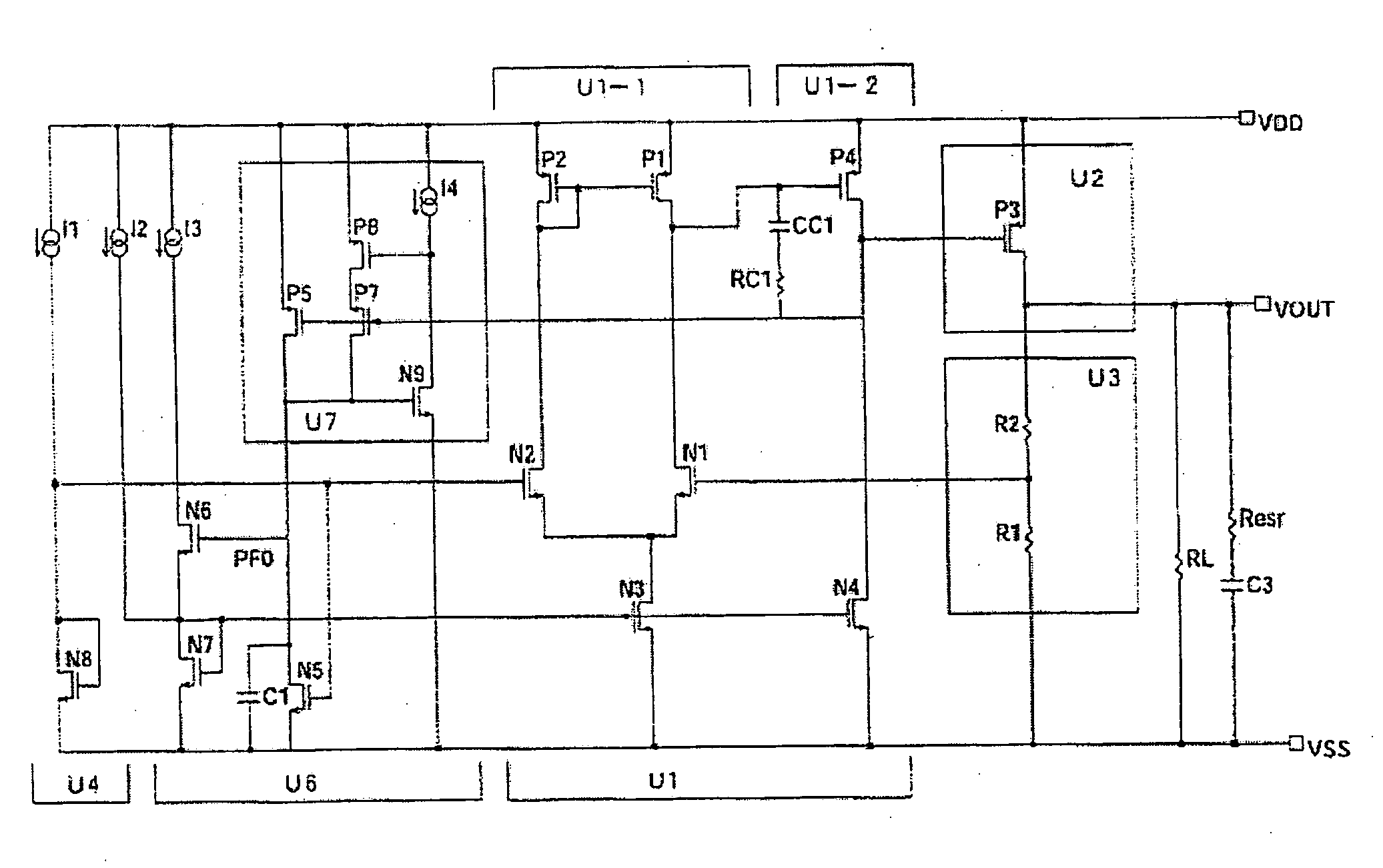
[0088]FIG. 6 is a block diagram showing the stabilized DC power supply circuit of the present invention, and FIG. 7 is a circuit diagram showing the specific circuit structure thereof. Vdd (VDD) and Vss (VSS) in FIGS. 6 and 7 are the power supply terminals. Moreover, I1 through I4 in FIG. 7 are the constant current sources, RL is the load resistance, C3 is the output decoupling capacitor, and Resr is the equivalent in-series resistance. Constant current sources I1 through I4 are actually formed from current mirror circuits, Zener diodes, and depression FETs.

[0089]The stabilized DC power supply circuit shown in FIGS. 6 and 7 comprises a differential amplifier U1, an output amplifier circuit U2, an output voltage dividing circuit U3, a reference voltage circuit U4, and an adaptive control bias current boost circuit U6. Of these structural elements, differential amplifier U1, output amplifier circuit U2, output voltage dividing circuit U3, and reference voltage circuit U4 have the same...

second embodiment

[0096]FIG. 12 is the basic circuit diagram showing the stabilized DC power supply circuit of the present invention. Vdd (VDD) and Vss (VSS) in FIG. 12 are the power supply terminals.

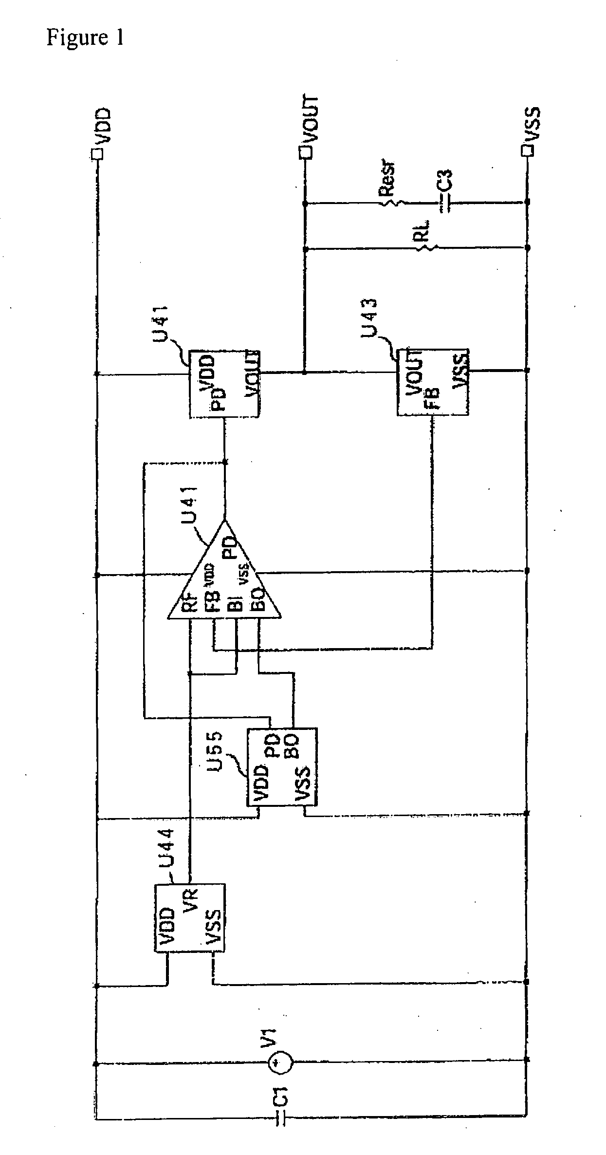
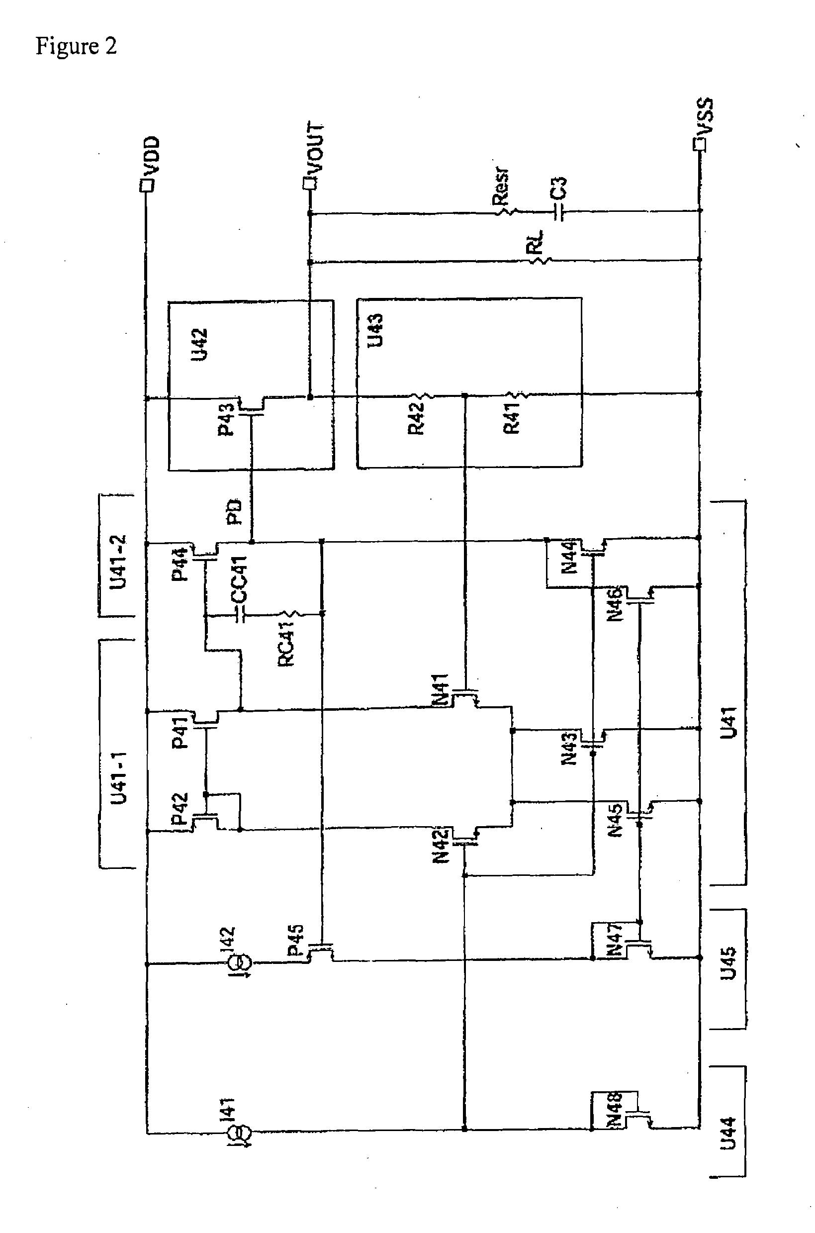
[0097]The stabilized DC power supply circuit in FIG. 12 comprises a differential amplifier U21, an output amplification circuit U22, an output voltage dividing circuit U23, a reference voltage circuit U24, and an adaptive control bias current boost circuit U26. Of these structural elements, differential amplifier U21, output amplification circuit U22, output voltage dividing circuit U23, and reference voltage circuit U24 have the same structure as differential amplifier U41, output amplification circuit U42, output voltage dividing circuit U43, and reference voltage circuit U44 of the conventional power supply circuit shown in FIGS. 1 and 2. In essence, differential amplifier U21 operates in such a way that it amplifies the difference in voltage between reference voltage circuit U24 and voltage dividing ...

third embodiment

[0102]FIG. 15 is a concrete circuit diagram showing the stabilized DC power supply circuit of the present invention. Vdd (VDD) and Vss (VSS) in FIG. 15 are the power supply terminals.

[0103]The stabilized DC power supply circuit shown in FIG. 15 comprises a differential amplifier U31, an output amplification circuit U32, an output voltage dividing circuit U33, a reference voltage circuit U34, and an adaptive control bias current boost circuit U36. Of these structural elements, differential amplifier U31, output amplification circuit U32, output voltage dividing circuit U33, and reference voltage circuit U34 have the same structure as differential amplifier U41, output amplification circuit U42, output voltage dividing circuit U43, and reference voltage circuit U44 of the conventional power supply circuit shown in FIGS. 1 and 2. In essence, differential amplifier U31 operates in such a way that it amplifies the difference in voltage between reference voltage circuit U34 and voltage di...


PUM


Abstract

A stabilized DC power supply circuit comprises an error amplifier circuit U1, an output amplifier circuit U2, an output voltage division circuit U3, and a reference voltage circuit U4. A bias current boost circuit U6 capable of stabilized operation is added to the DC power supply circuit. Since the feedback loop of the bias current boost circuit U6 is provided with a hysteresis function or an artificial hysteresis function by a large delay element, it is possible to adaptively control bias current without sacrifice of stability and realize a stabilized DC power supply circuit exhibiting high response and high stability with low current consumption.

Description

TECHNICAL FIELD[0001]The present invention relates primarily to a stabilized DC power supply circuit. In particular, it relates to a highly stable adaptively controlled stabilized DC power supply circuit that has quick response under low operation current.BACKGROUND ART[0002]Multiple stabilized DC power supply circuits are applied in portable electronic devices, as well as other so-called electronic equipments. Power supply circuits whose characteristics adapt to different purposes are used for digital circuits, high-frequency circuits, analog circuits, and the like. In case of a cellular phone, a very high power supply ripple rejection is required for a RF transmitting circuit because poor ripple rejection results in poor clearness of voice conversation. Power supply ripple noise has a detrimental effect on the error rate, even in the case of wireless communications means whereby information is converted to digital code and transmitted and received, because the carrier signals are ...

Claims


Application Information

Patent Timeline
Patent Type & Authority Applications(United States)
IPC IPC(8): G05F3/16G05F1/44
CPCG11C5/145G05F1/575
Inventor AKITA, SHINICHI
Owner NANOPOWER SOLUTION
Why Eureka
Try Eureka