Sequential Display With Motion Adaptive Processing for a Dmd Projector

a dmd projector and sequential display technology, applied in the field of sequential display operation, can solve the problems of increasing color breakup, affecting the quality of dmd projectors, and only working well for low brightness objects, so as to reduce motion blurring, reduce the incidence of motion blurring, and minimize color break-up

Inactive Publication Date: 2008-05-29
THOMSON LICENSING SA
View PDF10 Cites 0 Cited by
  • Summary
  • Abstract
  • Description
  • Claims
  • Application Information

AI Technical Summary

Benefits of technology

[0008]Briefly, in accordance with the present principles, there is provided a method for operating a color sequential display system having at least one pixel controlled by a pixel signal that determines pixel illumination during each of a plurality of segments of a picture period. The method commences by first determining from the pixel signal whether motion has occurred. If so, the pixel signal undergoes processing to initially substantially confine the change in illumination to a limited number of time-adjacent segments of the same color to reduce motion blurring. Confining the change in illumination to a limited interval during the picture period in the presence of motion reduces the incidence of motion blurring. In the absence of motion for more than a predetermined duration, the pixel signal undergoes processing to cause a substantially uniform distribution of illumination throughout the picture period for the associated pixel. Spreading the illumination substantially equally throughout the picture period minimizes color break-up with random, large and fast eye motion.

Problems solved by technology

A multiple segment display of the type described above can suffer from several different types of motion artifacts.
Unfortunately, this approach only works well for low brightness objects because higher brightness objects cannot be confined to one or two segments per color.
Moreover, confining an object, even a low brightness object, to one or two segments per color will increase color breakup caused by viewer eye motion

Method used


Image

  • Sequential Display With Motion Adaptive Processing for a Dmd Projector
  • Sequential Display With Motion Adaptive Processing for a Dmd Projector
  • Sequential Display With Motion Adaptive Processing for a Dmd Projector

Examples


Embodiment Construction

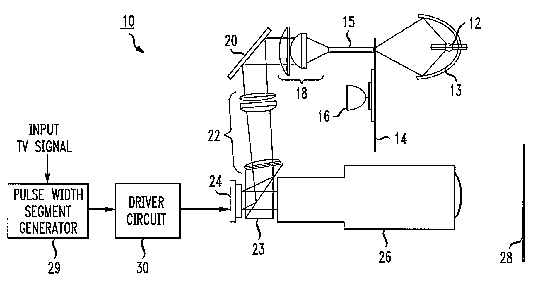
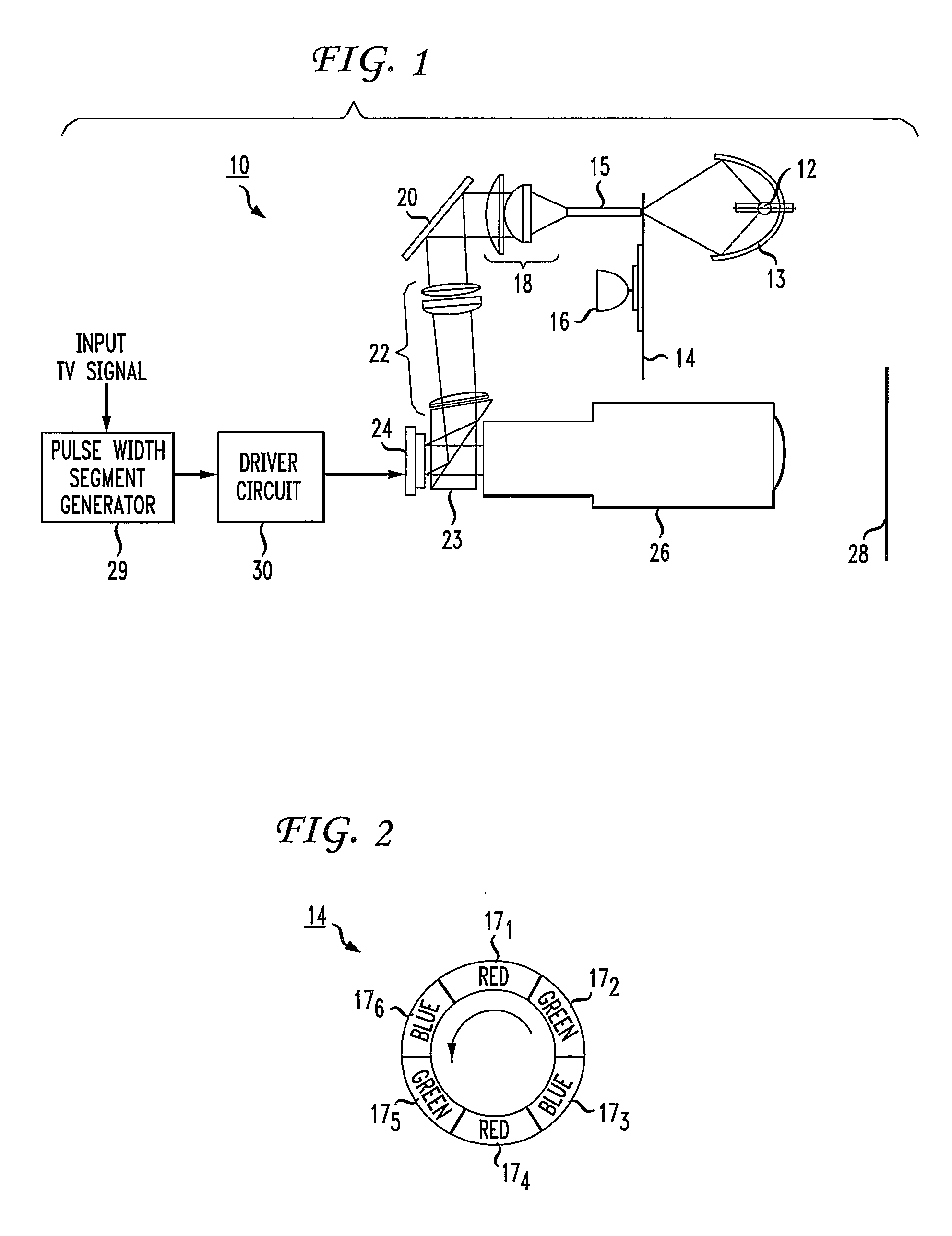
[0014]FIG. 1 depicts a present-day color sequential display system 10 of the type disclosed in the Application Report “Single Panel DLP™ Projection System Optics” published by Texas Instruments, June 2001 and incorporated by reference herein. The system 10 comprises a lamp 12 situated at the focus of an elliptical reflector 13 that reflects light from the lamp through a color wheel 14 and into an integrator rod 15. A motor 16 rotates the color wheel 14 to place a separate one of red, green and blue primary color windows between the lamp 12 and the integrator rod 15. In an exemplary embodiment depicted in FIG. 2, the color wheel 14 has diametrically opposed red, green and blue color windows 171 and 174, 172 and 175, and 173 and 176, respectively. Thus, as the motor 16 rotates the color wheel 14 of FIG. 2 in a counter-clockwise direction, red, green and blue light will strike the integrator rod 15 of FIG. 1 in an RGBRGB sequence. In practice, the motor 16 rotates the color wheel 14 at...


PUM


Abstract

Within a sequential display system, an apparatus performs motion adaptive processing of a pixel signal that controls the illumination of a corresponding pixel. The apparatus determines from the pixel signal whether motion has occurred for at least a predetermined duration. If not, the apparatus processes the pixel signal to cause a substantially uniform distribution of illumination throughout the picture period for the associated pixel. Otherwise, if motion has occurred for more than the predetermined duration, the apparatus processes the pixel signal to cause a substantial confinement of illumination to a limited interval of the picture period.

Description

TECHNICAL FIELD[0001]This invention relates to a technique for operating a sequential display to reduce artifacts.BACKGROUND ART[0002]There presently exist television projection systems that utilize a type of semiconductor device known as a Digital Micromirror Device (DMD). A typical DMD comprises a plurality of individually movable micromirrors arranged in a rectangular array. Each micromirror pivots about a limited arc, typically on the order of 10°-12° under the control of a corresponding driver cell that latches a bit therein. Upon the application of a previously latched “1” bit, the driver cell causes its associated micromirror to pivot to a first position. Conversely, the application of a previously latched “0” bit to the driver cell causes the driver cell to pivot its associated micromirror to a second position. By appropriately positioning the DMD between a light source and a projection lens, each individual micromirror of the DMD device, when pivoted by its corresponding dr...

Claims


Application Information

Patent Timeline
Patent Type & Authority Applications(United States)
IPC IPC(8): H04N5/74
CPCG09G3/2014G09G3/2025G09G3/2059G09G2320/0266G09G3/346G09G2320/0261G09G3/2077G02B26/10G03B21/00H04N5/74
Inventor WILLIS, DONALD HENRY
Owner THOMSON LICENSING SA
Why Eureka
Try Eureka