Focusing unit and ophthalmic photographing apparatus

a technology of focusing unit and ophthalmic photographing device, which is applied in the field of ophthalmic photographing device, can solve the problems of limited use of non-mydriatic fundus cameras, inability to change the optical axis of the light source for focusing, and achieve the effect of easily projecting an index onto a fundus

Inactive Publication Date: 2008-05-29
CANON KK
View PDF8 Cites 9 Cited by
  • Summary
  • Abstract
  • Description
  • Claims
  • Application Information

AI Technical Summary

Benefits of technology

[0010]The present invention provides a focusing unit, and an ophthalmic photographing apparatus capable of inserting and removing a focusing unit into and from an illumination light path and easily projecting an index onto a fundus.

Problems solved by technology

Therefore, the art of U.S. Pat. Appl. Pub. No. 2006 / 0077346 is limited to non-mydriatic fundus cameras.
In addition, the optical axis of the light source for focusing cannot be changed.

Method used


Image

  • Focusing unit and ophthalmic photographing apparatus
  • Focusing unit and ophthalmic photographing apparatus
  • Focusing unit and ophthalmic photographing apparatus

Examples


Embodiment Construction

[0028]Embodiments of the present invention will now be described with reference to the drawings.

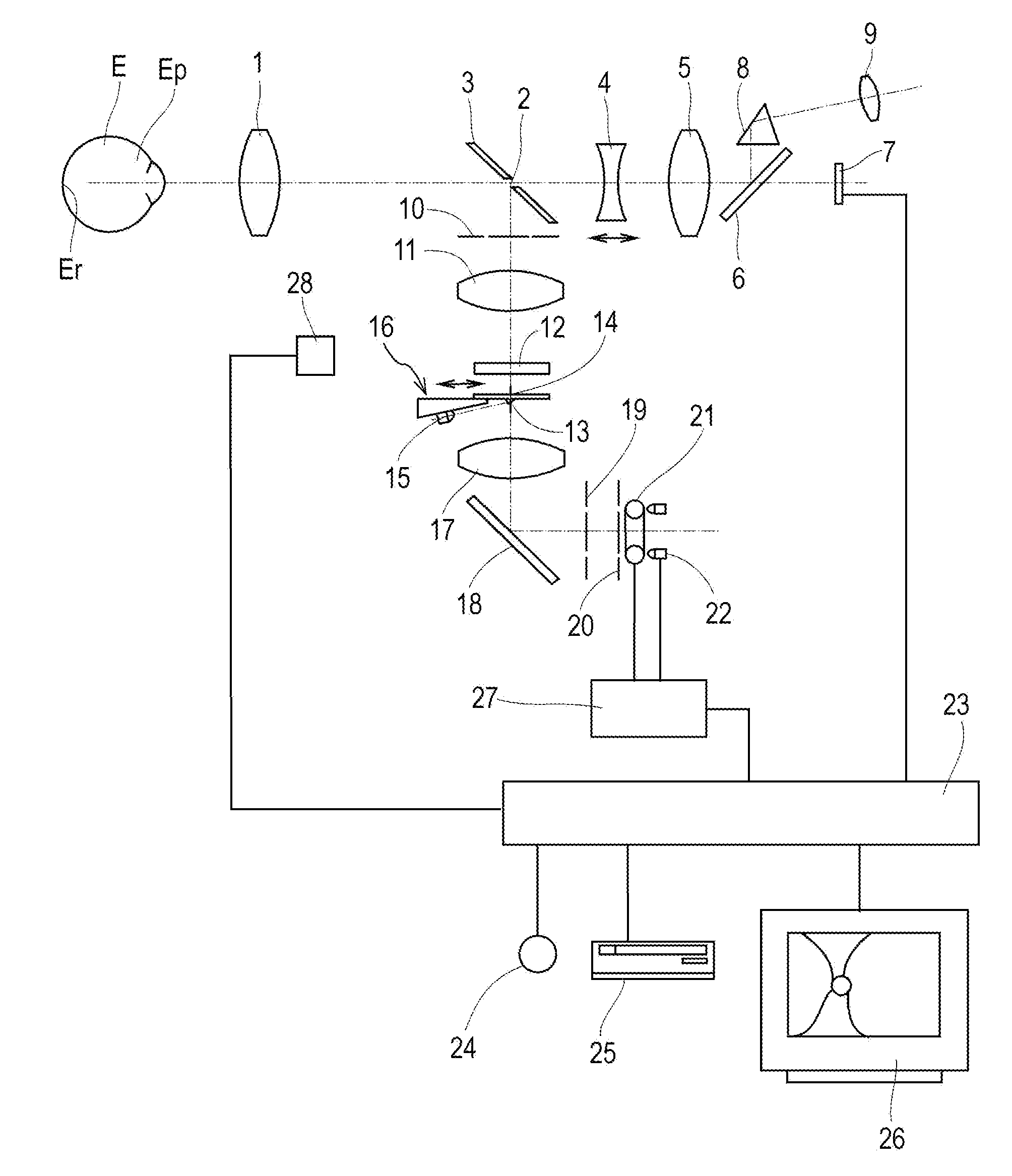
[0029]FIG. 1 shows the structure of a fundus camera. An objective lens 1, an apertured mirror 3 having a photographing aperture 2, a focus lens 4 for focusing, a photographing lens 5, and a quick return mirror 6 are disposed in front of a subject's eye E. An image pickup element 7 converts an optical image incident through the apertured mirror 3, the focus lens 4, the photographing lens 5, and the quick return mirror 6 into an electrical image signal. The focus lens 4, the photographing lens 5, the quick return mirror 6, and the image pickup element 7 constitute a photographing optical system. In the reflection direction of the quick return mirror 6 are arranged a reflection prism 8 and an ocular lens 9, which constitute an observation optical system.

[0030]An illumination optical system illuminating the fundus of the subject's eye E has a cornea diaphragm 10 for restricting below-describe...


PUM


Abstract

A focusing unit can be inserted into and removed from an illumination light path by rotating around a supporting portion. An index light source, a green LED, is attached to the bottom of a base. A transparent acrylic-resin disk is fixed to the base. A deflection prism is attached to the bottom of the disk. A beam from the light source enters the deflection prism. A focus index forming portion is provided on the top of the disk. In the center of a light-shielding portion is formed a slit-like opening, under which split prisms are provided. Deflected by the prisms, the beam from the light source is split into two, right-half and left-half, directional beams, and combined with an illumination optical system, in the form of two slit images, at the opening.

Description

BACKGROUND OF THE INVENTION[0001]1. Field of the Invention[0002]The present invention relates to an ophthalmic photographing apparatus used in opthalmologist's offices, clinics, and so forth.[0003]2. Description of the Related Art[0004]A fundus camera disclosed in Japanese Patent Laid-Open No. 5-95902 includes an index for focus indication, a light source that illuminates this index, and a projection optical system that has a split prism for projecting index images onto the fundus of a subject's eye from different positions of the pupil.[0005]In addition, there is also known a method such that a minute prism is provided in an illumination optical system, a slit image illuminated by fundus observation light is projected onto the fundus of an eye, and focus adjustment is performed as disclosed in Japanese Patent Laid-Open No. 6-142050.[0006]In the case of the above-described method, since both a focus index projection lens barrel and a minute mirror that branch from the illumination o...

Claims


Application Information

Patent Timeline
Patent Type & Authority Applications(United States)
IPC IPC(8): A61B3/14A61B3/12
CPCA61B3/14A61B3/00
Inventor TANAKA, SHINYAIWANAGA, TOMOYUKIITOH, HIROSHI
Owner CANON KK
Why Eureka
Try Eureka