Modeling device, program, computer-readable recording medium, and method of establishing correspondence

a technology of a modeler and a recording medium, applied in the field of modelers, can solve the problems of no modeling device to be realized, no coordinate system suitable for specifying the spots in the heart, and the shape of the heart is very complex

Active Publication Date: 2012-01-10
JAPAN MEDICAL DEVICE CORP
View PDF9 Cites 2 Cited by
  • Summary
  • Abstract
  • Description
  • Claims
  • Application Information

AI Technical Summary

Benefits of technology

[0020]Another object of the present invention is to realize a modeling device by which orientation characteristic information is easily projected from an object onto another object, which information is related to the shape of the object.
[0023]A spot in the object is specified on the basis of the electric potential obtained by the virtually electrifying means. The virtually electrifying means virtually applies the predetermined voltage. Therefore, the electric potential at a spot in the object is in the range of 0V to the predetermined voltage. Accordingly, a spot in the object is specified in the range of 0V to the predetermined voltage. This makes it possible to specify the spot in various objects having different shapes by use of a common scale (not smaller than 0V and not greater than the predetermined voltage). Accordingly, for example a function with a variable of a coordinate based on the electric potential is input to the second input section as the characteristic information, the characteristic is easily projected regardless of shape of a target object. In other words, with the modeling device of the present invention, the characteristic is projected onto various objects having different shapes. Further, no geometric calculation is necessary to specify the spot, so that the characteristic is easily projected onto an object even if the object has a complex shape.
[0026]The projecting means establishes the correspondence between the spot in the first object and the spot in the second object on the basis of the electric potential obtained by the virtually electrifying means. The virtually electrifying means applies the predetermined voltage. Therefore, the electric potential at a spot in the objects is in the range of 0V to the predetermined voltage. Accordingly, a spot in each of the objects is specified in the range of 0V to the predetermined voltage. This makes it possible to easily establish a correspondence by use of a common scale (not smaller than 0V and not greater than the predetermined voltage) even if the shape of the first object and the shape of the second object are complex and different. Accordingly, with the modeling device of the present invention, characteristic information obtained from an object is easily projected onto a differently-shaped object, even if the object, from which the characteristic information is obtained, has a complex shape. Further, no geometric calculation is necessary to establish a correspondence between spots, so that the characteristic is easily projected even if the shape of the object is complex.

Problems solved by technology

However, no modeling device has been realized by which information on the fiber orientation of the cardiac muscle cells, which information is obtained from an animal, is buried in a human heart to perform modeling suitably.
First, no coordinate system suitable to specify the spots in a heart has not been found.
Furthermore, the shapes of the hearts are very complex.
Therefore, it is extremely difficult with an ordinary XYZ-axes orthogonal coordinate system or the like to set a correspondence between spots of two different hearts.
Further, no method of suitably setting a local coordinate system to define the fiber orientation and the like at a spot in a heart has been found.
However, if the fiber orientation information is expressed with the use of an ordinary global coordinate system, it is not possible to express the fiber orientation in such a way as to correspond to the outer shape of the heart, because the global coordinate system has no relationship with the outer shape of the heart.
Therefore, if the fiber orientation data obtained from animals is directly applied to the human heart, contradiction may arise in the fiber orientation.
Further, even if a hypothesis about the fiber orientation on the basis of the findings obtained from the animal heart is to be applied, it is not possible to apply the hypothesis naturally.
The heart, however, has a very complex shape.
Setting the local coordinate system by performing a geometric calculation each time on the basis of the shape of the heart requires a vast amount of calculation and is therefore not realistic.

Method used


Image

  • Modeling device, program, computer-readable recording medium, and method of establishing correspondence
  • Modeling device, program, computer-readable recording medium, and method of establishing correspondence
  • Modeling device, program, computer-readable recording medium, and method of establishing correspondence

Examples


embodiment 1

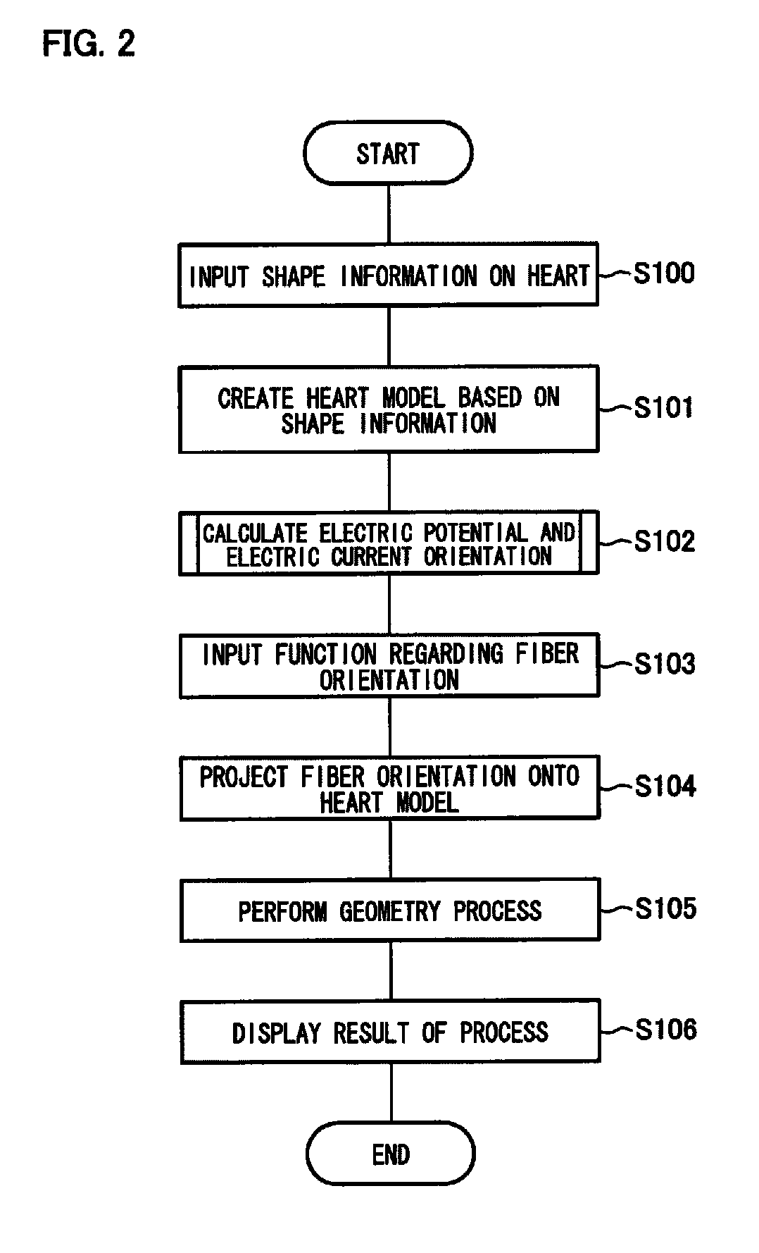
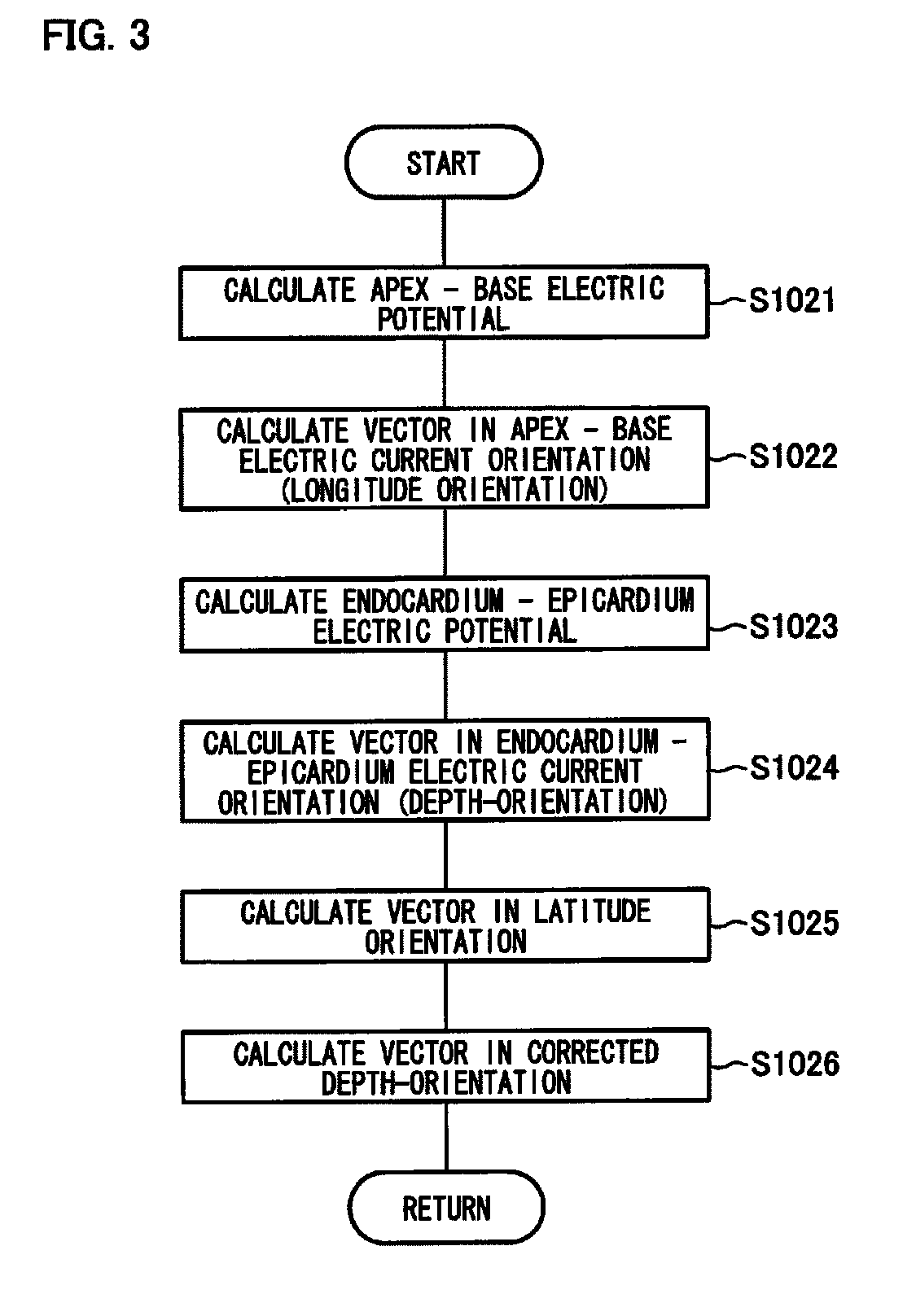
[0044]The following describes an embodiment of the present invention, with reference to FIGS. 1 to 8. In the present embodiment, an exemplary case is discussed in which an object is a human heart, and a characteristic employed is a characteristic regarding a fiber orientation of cardiac muscle cells. Specifically, a modeling device that suitably projects a hypothesis regarding the fiber orientation of the cardiac muscle cells onto a human heart model (more specifically, left ventricle model and right ventricle model) and reproduces a fiber orientation based on the hypothesis is described in the present embodiment.

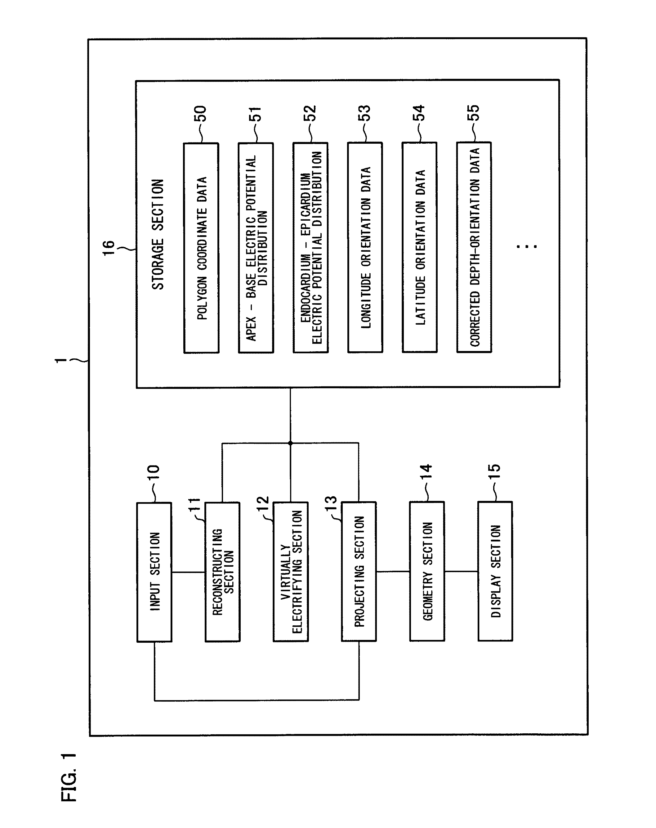
[0045]FIG. 1 is a functional block diagram of a modeling device 1 of the present embodiment. The modeling device 1 includes an input section (first input section, second input section) 10, a reconstructing section 11, a virtually electrifying section (electrifying means, virtually electrifying means) 12, a projecting section (projecting means) 13, a geometry section (geomet...

example 1

[0072]A heart model to which the hypothesis is applied is shown in FIGS. 8(a) to 8(e) as an Example of the modeling device of Embodiment 1. FIGS. 8(a) to 8(e) indicate the fiber orientations at spots where the apex—base electric potential is 0V, 0.25V, 0.5V, 0.75V, and 1V, respectively. The figures show how the fiber orientation changes continuously from the endocardium toward the epicardium, changing from −90° to +60°. Further, the respective fiber orientations fit in the shape of the heart.

embodiment 2

[0073]The following describes another embodiment of the present invention, with reference to FIGS. 9 and 10. In the present embodiment, a modeling device that projects fiber orientations of an animal heart onto a human heart model is described as an example. Components having equivalent functions as those of Embodiment 1 described above are given the same reference numerals, and description thereof is omitted.

[0074]FIG. 9 is a functional block diagram of a modeling device 2 of the present embodiment. The modeling device 2 includes an input section 20 (first input section, second input section, third input section) in place of an input section 10 of a modeling device 1 of Embodiment 1. Further, the modeling device 2 includes a storage section 26 in place of a storage section 16 of the modeling device 1 of Embodiment 1. Furthermore, the modeling device 2 includes a converting section (converting means) 27.

[0075]Shape information on a human heart (first object), shape information on an...


PUM

PropertyMeasurementUnit
lengthaaaaaaaaaa
lengthaaaaaaaaaa
electric potentialaaaaaaaaaa

Abstract

A modeling device is disclosed that easily projects characteristic information obtained from an object onto a differently-shaped object, even if the object, from which the characteristic information is obtained, has a complex shape. A modeling device in one embodiment of the present invention includes a virtually electrifying section to calculate an electric potential at a spot in a heart at the time when a predetermined voltage is applied to the heart, and a projecting section to project a fiber orientation onto a heart model created on the basis of shape information that is input to the input section. The projecting section specifies a spot to be a target of projection on the basis of the electric potential obtained by the virtually electrifying section. Use of the electric potential in specifying the spot makes it possible to easily project the fiber orientation onto any heart having complex and various shapes.

Description

TECHNICAL FIELD[0001]The present invention relates to a modeling device, a program, and a computer-readable recording medium, and particularly, relates to a modeling device virtually forming an object model, a program used in the modeling device, and a computer-readable recording medium storing the program. The present invention also relates to a method of establishing a correspondence between an object and another object.BACKGROUND ART[0002]A heart contracts and relaxes, that is to say, beats at a regular rhythm. Arrythmia is a serious disease that a period of this cardiac beat becomes irregular, sometimes causing cardiac arrest. Various and detailed studies have been carried out on the cardiac beat mechanism for medical treatment and diagnosis of arrythmia.[0003]Cardiac contraction occurs as follows. First, electrical impulses are emitted at a constant period from a part of a right atrium, which part is called a sinoatrial node. The electrical impulses are passed to cardiac muscle...

Claims


Application Information

Patent Timeline
Patent Type & Authority Patents(United States)
IPC IPC(8): G01N33/48G06F7/60G01N33/50G06F17/50A61B5/04A61B5/107
CPCG06F19/3437G06T11/206G16H50/50
Inventor HISADA, TOSHIAKIKUROKAWA, HIROSHIOSHIDA, NOBUHIKOYAMAMOTO, MASAFUMIWASHIO, TAKUMIOKADA, JUN-ICHIWATANABE, HIROSHISUGIURA, SEIRYO
Owner JAPAN MEDICAL DEVICE CORP
Why Eureka
Try Eureka