
System and method for total internal reflection enhanced imaging flow cytometry

a flow cytometry and enhanced imaging technology, applied in the direction of instruments, material analysis, investigating moving fluids/granular solids, etc., can solve the problems of poor signal quality, high autofluorescence, and weak particle fluorescence, so as to improve sample fluorescence signal integrity and strength, improve fluorescence measurement, and improve sample fluorescence results

Active Publication Date: 2014-11-04
YOKOGAWA FLUID IMAGING TECH INC
View PDF30 Cites 4 Cited by
  • Summary
  • Abstract
  • Description
  • Claims
  • Application Information

AI Technical Summary

Benefits of technology

The present invention is an improved imaging flow cytometry system and method that enhances sample fluorescence signal integrity and strength. It utilizes a properly dimensioned flow cell with internal reflections to achieve better fluorescence measurements than conventional instruments. The system includes a laser fan generator, an imaging and excitation objective, a high aspect ratio rectangular glass flow cell, a high numerical aperture fluorescence emission collecting objective, and fluorescence emission analysis optics. The glass flow cell allows the fluorescence emissions from the sample to reflect back and forth within the sample until it emerges from the edge of the flow cell onto the fluorescence analysis optics. This configuration efficiently collects fluorescence from passing particles over a large position range without focus affecting the signal strength. The use of the system and method also removes system autofluorescence, which permits higher system gain and laser power, and greater sensitivity.

Problems solved by technology

The inefficiencies of standard methods of collecting light from a rectangular flow cell with laser fan illumination can result in weak particle fluorescence which varies greatly with particle position within the flow cell due to the sensitivity of the optics to different optical paths taken by the light on its way to the detector.
This poor signal quality is accompanied by high autofluorescence from optical components in existing instruments.

Method used


Image

  • System and method for total internal reflection enhanced imaging flow cytometry
  • System and method for total internal reflection enhanced imaging flow cytometry
  • System and method for total internal reflection enhanced imaging flow cytometry

Examples


Embodiment Construction

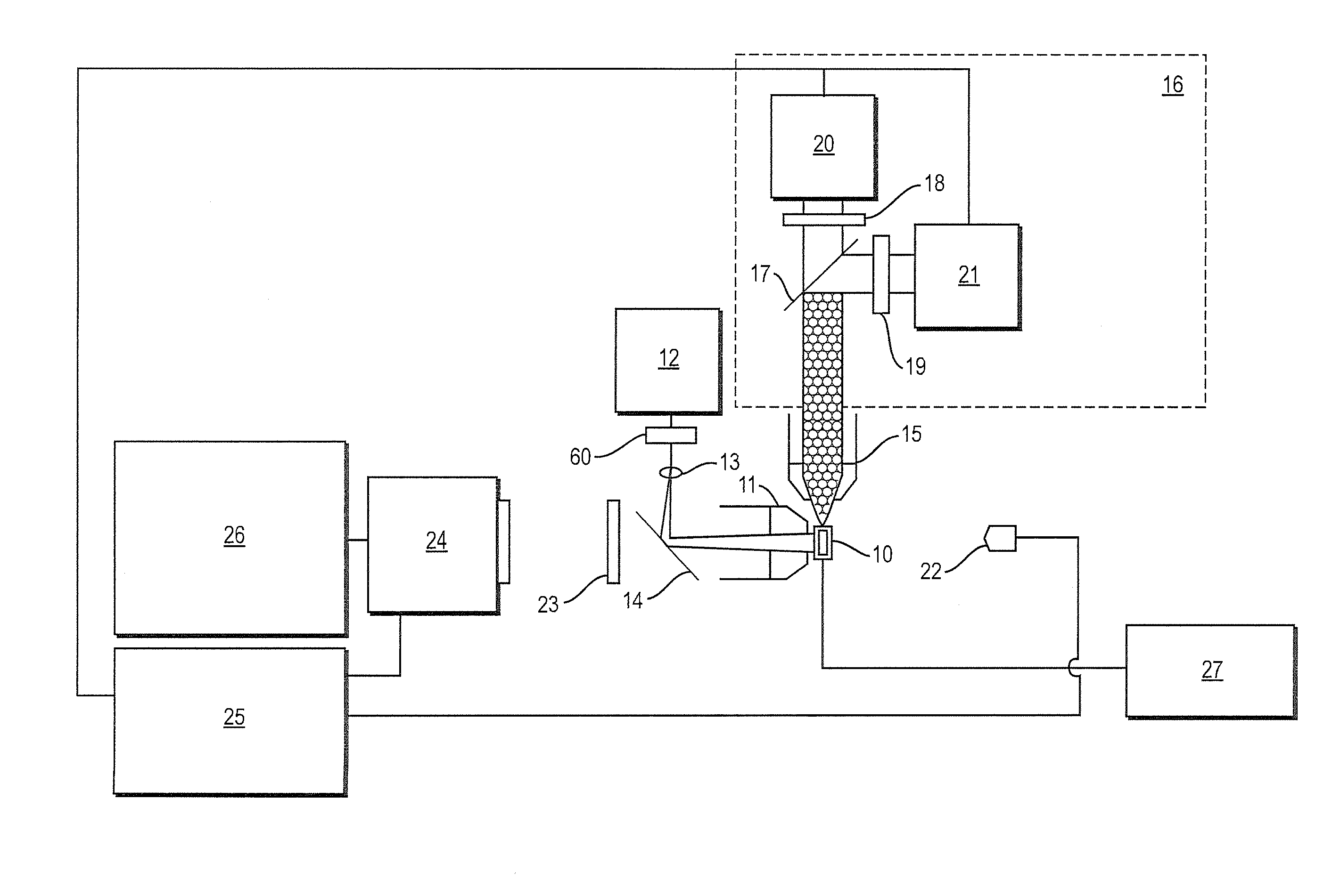
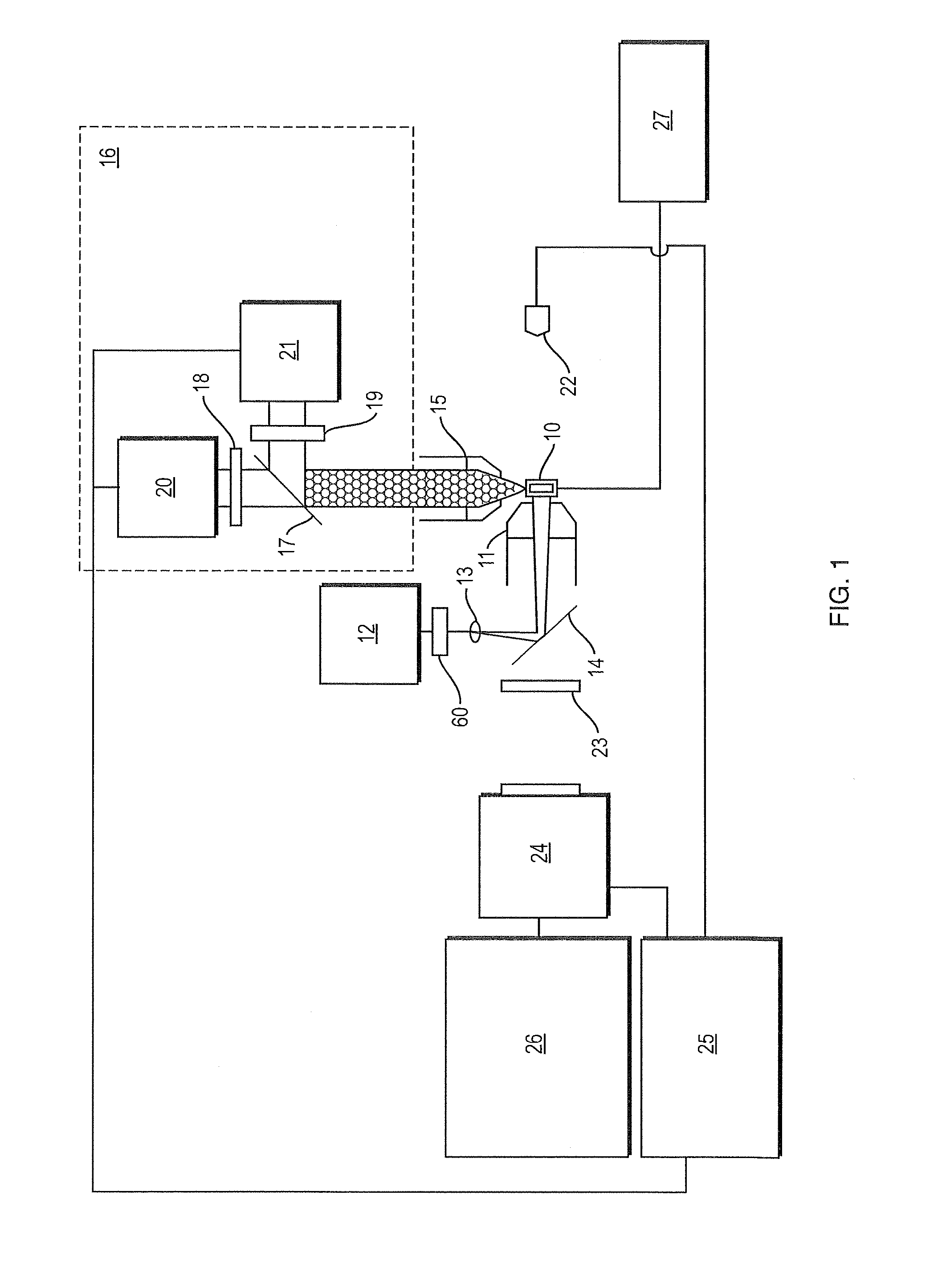
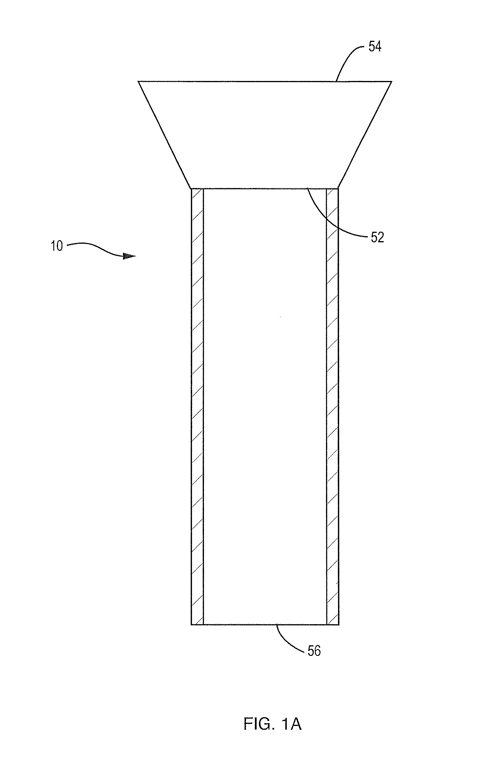
[0016]One embodiment of a system of the present invention suitable for high sensitivity automated counting and / or imaging of particles in a fluid is shown in FIG. 1. The system includes a flow chamber 10, which is shown alone in FIG. 1A, an imaging and excitation objective 11, a laser 12, a laser fan generator lens 13, a laser reflecting mirror 14, a fluorescence emission objective 15, fluorescence analysis optics 16, including one or more mirrors represented by longpass dichroic mirror 17, optical filters 18,19 and photomultipliers 20,21, a backlighting source 22, a laser blocking filter 23, an image capturing system 24, a digital signal processor 25, a computing device 26 and a pump 27 capable of delivering a controllable fluid flow rate. The embodiment of the system 10 depicted in FIG. 1 may also include other imaging and analysis in other possible configurations.

[0017]As shown in FIG. 2, the flow chamber 10 includes an inlet for receiving the particle containing fluid to be obse...


PUM


Abstract

An imaging flow cytometry system and method which includes a flow chamber, fluorescence analysis and imaging optics, image capturing system, device to regulate fluid flow through the chamber, and backlighting generator. The flow cell is configured so as to enhance the fluorescence signal collection by the system with total internal reflections. The fluorescence collection optics are configured to enhance the collection of the fluorescence from the side of the flow cell and concentrate it on light detectors.

Description

FIELD OF THE INVENTION[0001]The present invention relates generally to an optical flow imaging and analysis configuration used in particle analysis instrumentation, and more particularly to an optical flow imaging system and method incorporating a flow chamber that provides total internal reflections (TIR) of particle fluorescence, enabling more sensitive measurements than previously enabled.BACKGROUND OF THE INVENTION[0002]Various optical / flow systems employed for transporting a fluid within an analytical instrument to an imaging and optical analysis area exist in the art. A liquid sample is typically delivered into the bore of a flow chamber and the sample is interrogated in some way so as to generate analytical information concerning the nature or properties of the sample. For example, a laser beam may excite the sample present in the bore of the flow cell, and the emitted fluorescence energy provides signal information about the nature of the sample.[0003]If the system is design...

Claims


Application Information

Patent Timeline
Patent Type & Authority Patents(United States)
IPC IPC(8): G06K9/00G06V10/145G06V10/147
CPCG01N15/1436G01N21/53G01N21/47G01N21/6456G06K9/2036G06K9/209G01N2021/6493G01N2201/062G01N21/85G01N15/1427G06V10/145G06V10/147
Inventor SIERACKI, CHRISTIAN K.PETERSON, KENT A.DUPLISEA, MATTHEW A.DRAKE, CORIE F.
Owner YOKOGAWA FLUID IMAGING TECH INC
Learn More