Projection optical system and projector apparatus

a technology of projection optical system and projector, which is applied in the direction of projectors, mountings, instruments, etc., can solve the problems of not easy to provide a system with a design, and achieve the effects of reducing the movement distance of the first focus lens group, suppressing interference, and easy suppressing fluctuations in image formation performan

Active Publication Date: 2017-10-10
NITTO OPTICAL CO LTD
View PDF21 Cites 5 Cited by
  • Summary
  • Abstract
  • Description
  • Claims
  • Application Information

AI Technical Summary

Benefits of technology

[0005]In this projection optical system, the first refractive optical system forms a first intermediate image, the second refractive optical system forms the first intermediate image into a second intermediate image on the enlargement side, and the second intermediate image is enlarged and reflected by the first reflected surface. It is not easy to provide a system with a design where the aberration produced when the second intermediate image is enlarged and reflected is corrected at the first reflective surface. But, in this projection optical system, the second refractive optical system can form the second intermediate image so as to curvature of field and the like produced by the first reflective surface are corrected, and the first refractive optical system can form a first intermediate image in which coma aberration and the like produced by the second refractive optical system are corrected. Accordingly, it is easy to project sharp enlarged images. In addition, in this projection optical system, when carrying out focusing, a first focus lens group including at least one lens out of the second refractive optical system is moved. By this focus lens group, it is easy to form a second intermediate image where fluctuations in aberration that accompany changes in the projection distance and the like are corrected and easy to suppress fluctuations in the image formation performance for the projected images.
[0014]In this projection optical system, according to Condition (1), the second refractive optical system has a larger correction effect for curvature of field than the first refractive optical system, according to Condition (2), the second refractive optical system has a larger correction effect for distortion than the first refractive optical system, and according to Condition (3), the correction effect for coma aberration is substantially equal for the first refractive optical system and the second refractive optical system. This means that it is possible to reduce the correction load of the second refractive optical system. Accordingly, it is possible to simplify the configuration of the second refractive optical system and to make the second refractive optical system compact.

Problems solved by technology

It is not easy to provide a system with a design where the aberration produced when the second intermediate image is enlarged and reflected is corrected at the first reflective surface.

Method used


Image

  • Projection optical system and projector apparatus
  • Projection optical system and projector apparatus
  • Projection optical system and projector apparatus

Examples


first embodiment

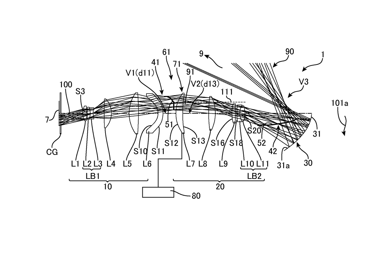
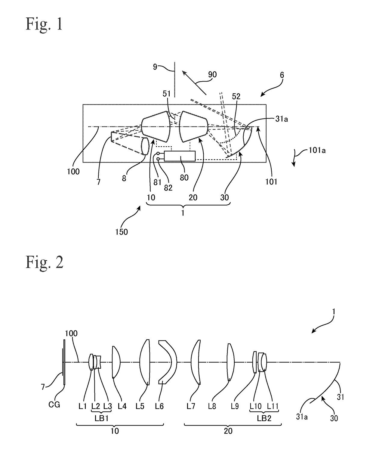
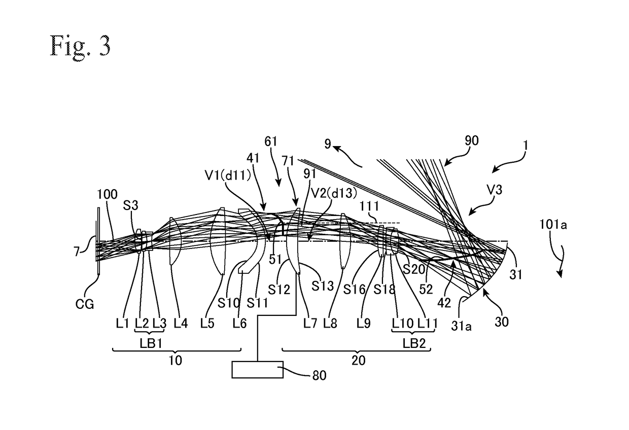
[0045]FIG. 2 shows the projection optical system 1 according to a FIG. 3 shows a light ray diagram of the projection optical system 1. This projection optical system 1 is a fixed focus (single focus)-type projection optical system that is non-telecentric on the incident (reducing) side and does not carry out zooming. The projection optical system 1 includes, in order from the side of the DMD 7 on the reducing side, the first refractive optical system 10 that includes six lenses L1 to L6, the second refractive optical system 20 that includes five lenses L7 to L11, and the first reflective optical system 30 that includes a single mirror (concave mirror) 31 equipped with the first reflective surface 31a. In the projection optical system 1, the image formed on the light valve 7 that is the first image plane is enlarged and projected by the first refractive optical system 10, the second refractive optical system 20, and the first reflective optical system 30 onto the screen 9 that is th...

second embodiment

[0071]FIG. 10 shows a projection optical system 2 according to a FIG. 11 is a ray diagram of the projection optical system 2. The projection optical system 2 is a fixed focus (single focus)-type projection optical system that is telecentric on the incident side (reducing side) and does not carrying out zooming. The projection optical system 2 includes the first refractive optical system 10 that includes twelve lenses L1 to L12, the second refractive optical system 20 that includes six lenses L13 to L18, and the first reflective optical system 30 that includes a single mirror (concave mirror) 31 with the first reflective surface 31a, disposed in that order from the DMD 7 side on the reducing side. In the projection optical system 2 also, images formed on the DMD 7 that is the first image plane are enlarged and projected onto the screen 9 that is the second image plane by the first refractive optical system 10, the second refractive optical system 20, and the first reflective optical...

third embodiment

[0087]FIG. 18 shows a projection optical system 3 according to a The projection optical system 3 is a projection optical system of a type where the projection optical system 2 is bent midway in the first refractive optical system 10. The first refractive optical system 10 of the projection optical system 3 includes a mirror 95 that bends the optical axis 100 at substantially a right angle in a space between the positive lens L8 and the positive lens L9. In the projection optical system 3, by having the mirror 95 bend the first refractive optical system 10, it is possible to reduce the overall length of the projection optical system 3. In addition, by disposing the illumination optical system 8 and the focusing mechanism 80 in a space 99 formed by bending the first refractive optical system 10, it is possible to miniaturize a projector 6 including the projection optical system 3, the illumination optical system 8, and the like.

[0088]FIG. 19 shows a projection optical system 4 accord...


PUM


Abstract

A projection optical system (2) projects from a DMD (7) on a reducing side onto a screen (9) on an enlargement side, and includes: a first refractive optical system (10) that forms a first intermediate image (51) on the enlargement side using light incident from the reducing side; a second refractive optical system (20) that forms the first intermediate image (51) on the reducing side into a second intermediate image (52) on the enlargement side; and a first reflective optical system (30) including a first reflective surface (31a) with positive refractive power that is positioned on the enlargement side of the second intermediate image (52), wherein the second refractive optical system (20) includes a first focus lens group (61) that moves when focusing is carried out, and the first focus lens group (61) includes at least one lens (L13) included in the second refractive optical system (20).

Description

TECHNICAL FIELD[0001]The present invention relates to a projection optical system of a projector apparatus.BACKGROUND ART[0002]Japanese Laid-Open Patent Publication No. 2004-258620 (hereinafter “Document 1”) discloses the realization of a projection optical system which, in addition to using an image forming optical system including a reflective surface to increase the size on the screen of projected images while reducing the projection space outside a projector apparatus, is capable of correcting chromatic aberration and also an image projecting apparatus that uses such projection optical system. To do so, Document 1 discloses that a first and second optical system are disposed in that order from a light valve on the projection side of the light valve, the first optical system includes at least one refractive optical system and has positive refractive power, the second optical system includes at least one reflective surface with refractive power and has positive refractive power, a...

Claims


Application Information

Patent Timeline
Patent Type & Authority Patents(United States)
IPC IPC(8): G03B21/53G03B21/00G02B13/16G02B17/08G02B7/04G02B7/02G03B21/28
CPCG03B21/53G02B7/028G02B7/04G02B17/08G02B17/0896G03B21/005G02B13/16G03B21/28
Inventor MATSUO, TAKAHIKO
Owner NITTO OPTICAL CO LTD
Why Eureka
Try Eureka