Light-guide plate, area light source apparatus and image reading apparatus

a technology of light guide plate and area light source, which is applied in the direction of mechanical equipment, lighting and heating equipment, instruments, etc., can solve the problems of difficult to smoothly work the die, easy to cause scratches and defects, and generate unnecessary scattered light having an emission line, etc., to reduce the number of products during working, reduce processing time, and facilitate the effect of automation

Inactive Publication Date: 2008-05-29
NIPPON SHEET GLASS CO LTD
View PDF16 Cites 3 Cited by
  • Summary
  • Abstract
  • Description
  • Claims
  • Application Information

AI Technical Summary

Benefits of technology

[0024]Accordingly, it is one object of the present invention to provide a light-guide plate whereby unnecessary scattered light is not caused even if it is easily molded and its thickness is made thin, and a area light source apparatus using the light-guide plate.
[0025]Also, it is another object of the present invention to provide a area light source apparatus in which the using efficiency of light is increased and the luminance is improved by suppressing, as much as possible, the absorption and the transmission of light with a reflecting base material adhered to a rear surface side and a side surface of a light-guide plate and by re-inputting most part of the light inputted to the reflecting base material to the light-guide plate.
[0026]Further, it is another object of the present invention to provide a area light source apparatus capable of saving the time and the number of assembling processes by omitting the reverse of a worked product during a working process, and an image reading apparatus using the area light source apparatus.
[0028]According to the present invention, the edge portion and the corner portion of the light-guide plate are convexly curved, therefore, the die is easily formed, and the number of scratches of the edge portion in light-guide plate can be reduced. Since the number of scratches of the edge portion in the light-guide plate, to which the die is transferred, can be reduced and the light-guide plate can easily be pull out from the die, the number of scratches which are conventionally caused is reduced and the scattered light due to the scratch can be reduced. The concentration of the light at the edge portion and the corner portion is suppressed and, therefore, the generation of the scattered light from the edge portion and the corner portion can be suppressed. Furthermore, the edge portion and the corner portion of the light-guide plate are convexly curved and, hence, high temperature and high pressures are unnecessary to fill the edge portion with a material upon die molding even if the thickness of the light-guide plate is thin, and the problem in that the increase in temperature reduces the transparency can be solved.
[0030]In the present invention, the reflecting plate having the high reflectance is arranged on a rear surface of the light-guide plate or on the rear surface thereof and a side surface, most light outputted from the rear surface of the light-guide plate is returned to the light-guide plate. In other words, since the light can be re-inputted to the light-guide plate, the using efficiency of light of the light source can be increased and, further, the luminance of the area light source apparatus can finally be improved.
[0033]In the present invention, when the light source is mounted on the light-guide plate, an adhering process with an adhesive is not required and it is unnecessary to wait for a time during which the adhesive is dry. Accordingly, a processing time can be reduced and the number of products during working can be decreased. Further, a part is fitted into the case frame from a single direction and, therefore, the reverse of a worked product during a working process is not required, it is troublesome for the working, and the automation of processes is easy.

Problems solved by technology

However, the thinner light-guide plate causes a problem in that the light is concentrated at an edge (side) portion and a corner portion of the light-guide plate 40 and strong scattered-light is generated from the edge portion and the corner portion.
Further, a scratch and defects due to die molding are easily caused near the edge portion and the corner portion.
The scratch and the defects due to the die molding cause a problem in that unnecessary scattered light having an emission line is generated.
Therefore, it is difficult to smoothly work the die including an end part of the edge portion with the right angle.
This causes a problem in that the increase in temperature reduces the transparency of the material.
The scattering reflecting plate, which is usually used as a reflecting base material, has no mirror surface but finely concave and convex portions on a front surface thereof, which result in light scattering reflection.
As described in FIG. 3, since the conventional area light source apparatus is structured by adhering the LED module to the inner surface of the case frame with the adhesive, there is a problem in that it takes a long time to make the adhesive dry and to completely adhere the LED module to the inner surface of the case frame and the number of products is increased during working and before the adhesive is dry.
Consequently, there is also a problem in that the reverse of a worked product is necessary during the working process, it is troublesome, and the automation is difficult.

Method used


Image

  • Light-guide plate, area light source apparatus and image reading apparatus
  • Light-guide plate, area light source apparatus and image reading apparatus
  • Light-guide plate, area light source apparatus and image reading apparatus

Examples


first embodiment

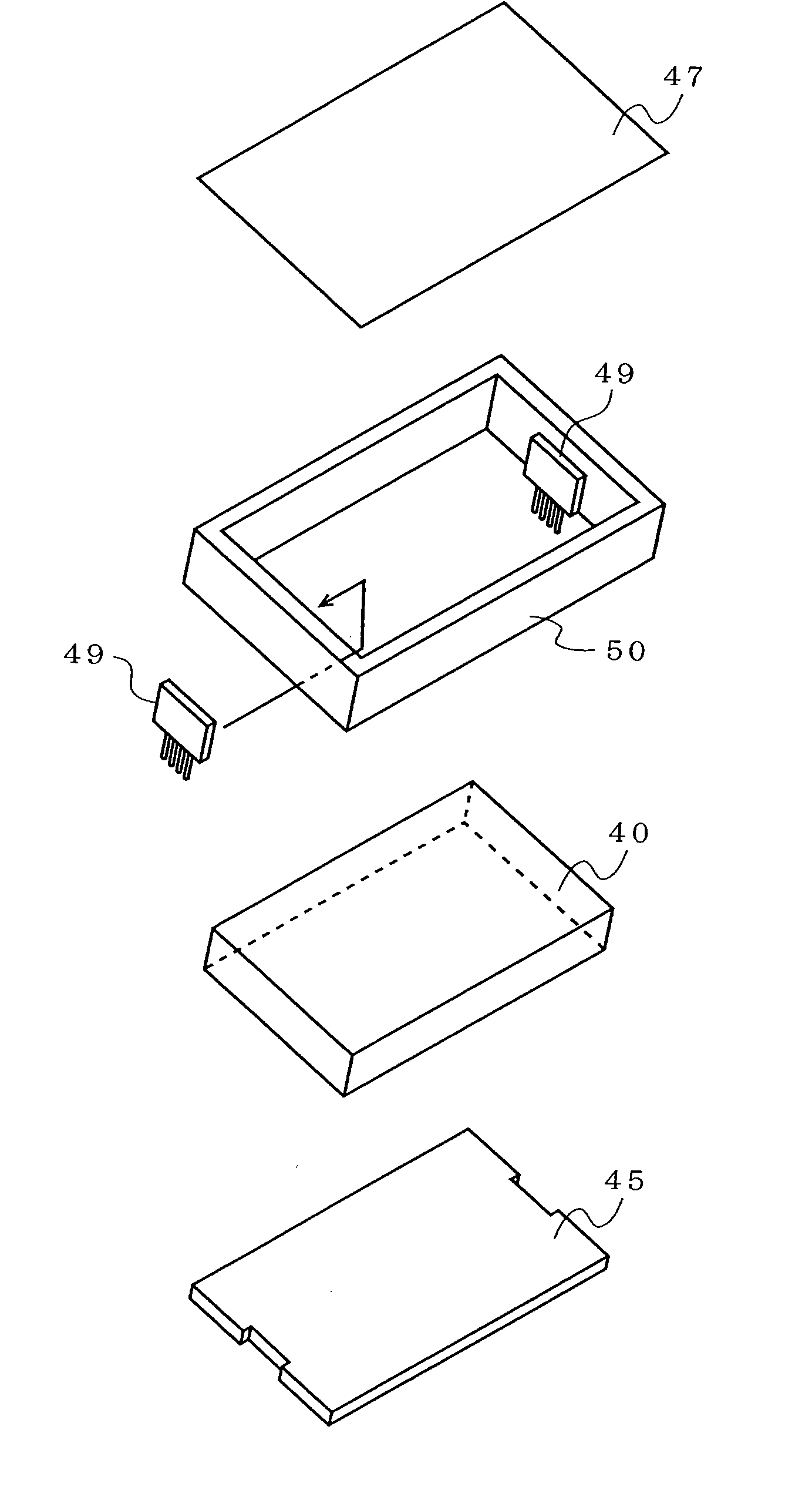
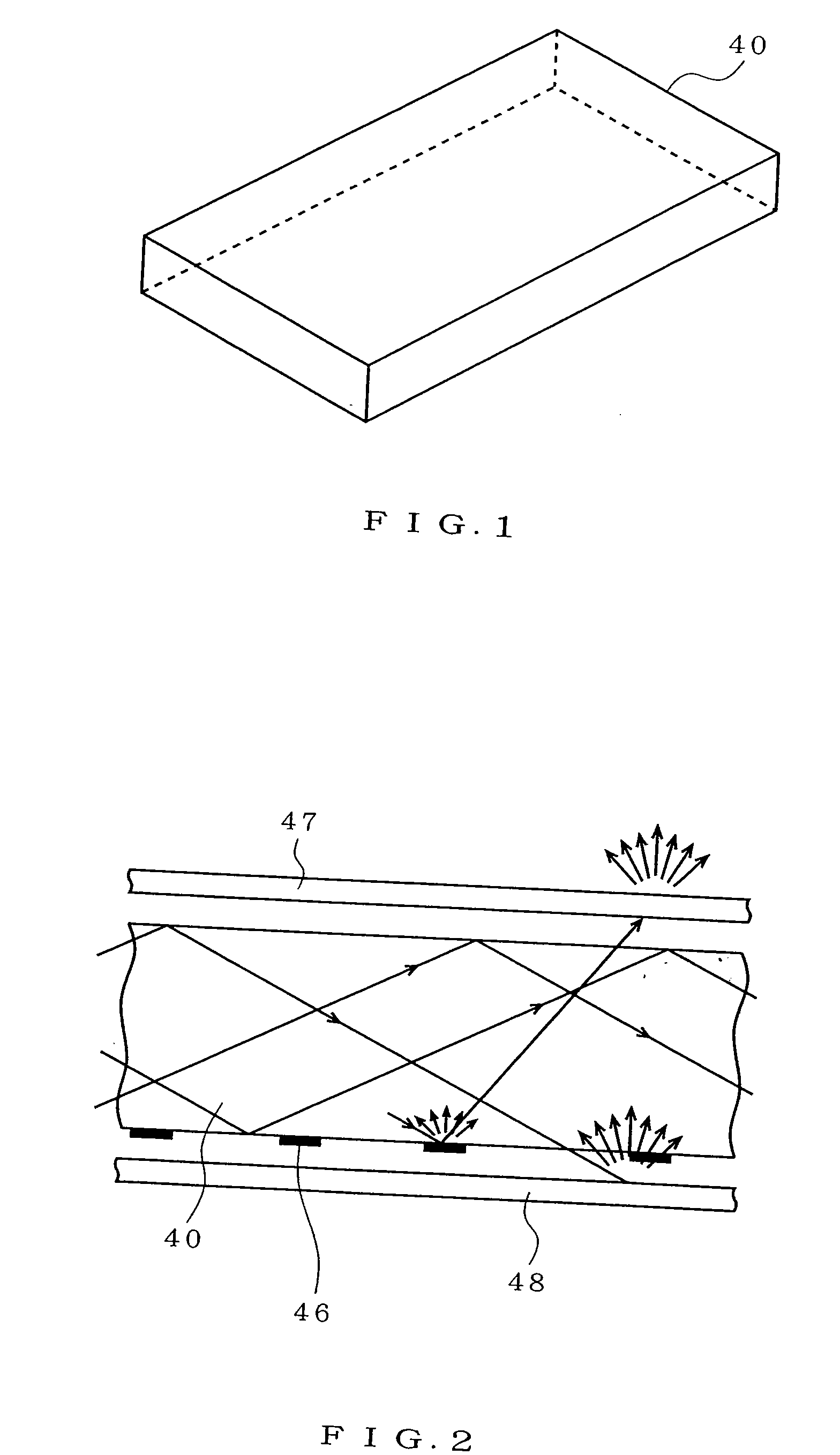
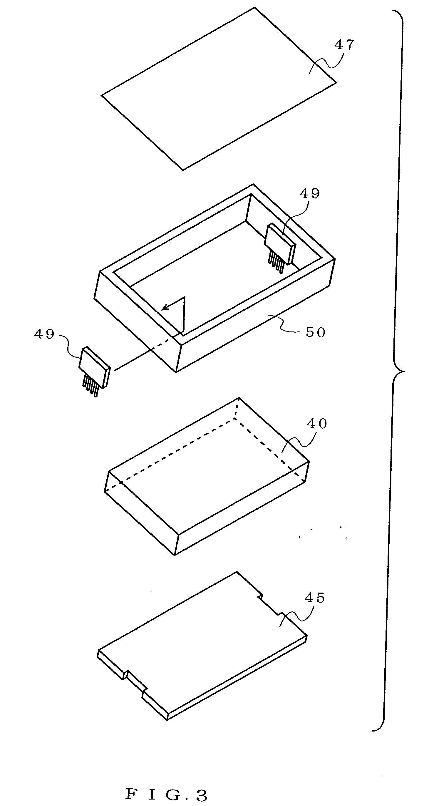
[0075]FIG. 6 is an exploded perspective view of a area light source apparatus according to the present invention. The area light source apparatus shown in FIG. 6 comprises: a light-guide plate 1 which is planar- and rectangular-shaped; case frames 3a and 3b; an LED module 2 as a light source; and a light scattering sheet 4 arranged at an upper surface of the light-guide plate 1.

[0076]An edge (side) portion and a corner portion of the light-guide plate 1 is convexly shaped. The light-guide plate 1 is made of transparent materials such as an acrylic material and glass. FIG. 7 is an enlarged view of the edge portion and the corner portion of the light-guide plate shown in FIG. 6. A diagonal line represents a sectional shape. Referring to FIG. 7, a side, at which side surfaces of the light-guide plate 1 are made contact, is curve-chamfered. Further, sides, at which an upper surface and a side surface of the light-guide plate 1 are made contact, and sides at which a bottom surface and th...

second embodiment

[0112]The reflecting plate having the high reflectance is sandwiched between the light-guide plate and the case frame in the However, advantageously, the surface is processed so that the inner surface of the case frame surrounding the light-guide plate has a high reflectance, for example, the surface is buffed or the high-reflectance film is adhered to the inner surface of the case frame. Further, advantageously, the reflecting plate is arranged only on the rear surface of the light-guide plate.

[0113]The reflecting plate is arranged at the light-guide portion (on the rear surface and the side surface) of the light-guide plate. However, obviously, light which is outputted to the outside is re-inputted to the light-guide plate, is effectively used, and the luminance is increased by providing the reflecting plate on both opposed surfaces, though this phenomenon is different because most light which has reached to the opposed surfaces of the mounted surface of the LED module, directly ...

third embodiment

[0127]FIG. 19A shows a method for positioning the LED module by using the pin, that is, the method shown in FIG. 18 according to the

[0128]Referring to FIG. 19A, the three pins 15 are formed on a side surface in a direction perpendicular to a longitudinal direction of the light-guide plate 11, integrally with the light-guide plate 11 or separately therefrom. The holes 17 are formed at positions corresponding to the pins 15 in the LED modules 12. The LED module 12 is positioned to the light-guide plate 11 by piercing the pins 15 into the holes 17.

[0129]The two pins 15 of the three ones are formed horizontally to an upper surface of the light-guide plate 11. The remaining one is formed, not linear-symmetrically to a center line of the side surface in a height direction. Because erroneous mounting of a rear side and a front side of the LED module 12 is prevented to correctly mount the LED module 12.

[0130]Incidentally, in this example, the number of pins is three and a concave portion (n...


PUM


Abstract

An LED module is mounted on a case frame by fitting three pins formed at a concave portion of the case frame, into holes in the LED module corresponding to the pins. A light-guide plate is fitted into the case frame formed integrally with a bottom cover in a descending direction. The light-guide plate is fixed by a hook provided for the case frame. A space between the light-guide plate and the LED module is prevented by pressing the light-guide plate to the LED module with a pressing spring. Since the light-guide plate is fitted into the case frame in the descending direction and a light scattering sheet is adhered to an outer end surface of the case frame in the descending direction, it is not necessary to reverse the worked product and so the number and time of working processes can be saved.

Description

BACKGROUND OF THE INVENTION[0001]1. Field of the Invention[0002]The present invention relates to a area light source apparatus using an LED (Light Emitting Diode) and a light-guide plate, and an image reading apparatus using the area light source apparatus.[0003]2. Description of the Related Art[0004]In recent years, a area light source apparatus using an LED and a light-guide plate has been manufactured. The area light source apparatus has been used as a light transmitting unit in a CIS (Contact Image Sensor)-type image scanner, etc.[0005]FIG. 1 is a diagram showing the appearance of a light-guide plate used for a conventional area light source apparatus. Referring to FIG. 1, a light-guide plate 40 is planar- and rectangular-shaped. A light-guide plate 40 uses transparent materials such as acrylic materials and glass. An LED module as a light source is arranged on a side surface of the light-guide plate 40. A light scatterer (printing dot) pattern is formed on a rear surface of the...

Claims


Application Information

Patent Timeline
Patent Type & Authority Applications(United States)
IPC IPC(8): F21V8/00H04N1/028
CPCG02B6/0043G02B6/0073G02B6/0088H04N2201/02479H04N1/02835H04N1/0289H04N2201/02462H04N1/02815
Inventor FUJINO, KOUZOUIKEDA, MAKOTOSAITOU, TOMIHISA
Owner NIPPON SHEET GLASS CO LTD
Why Eureka
Try Eureka