Fuel cell

a fuel cell and cell technology, applied in the field of fuel cells, can solve the problems of reducing output, difficult to fix the attitude during use, and insufficient output characteristics, and achieve the effects of reducing the imbalance of distribution, enhancing output characteristics, and increasing the life of cells

Inactive Publication Date: 2008-05-29
KK TOSHIBA
View PDF5 Cites 5 Cited by
  • Summary
  • Abstract
  • Description
  • Claims
  • Application Information

AI Technical Summary

Benefits of technology

[0012]The present invention has been developed in view of the above-mentioned problems that may occur in a passive fuel cell that does not use transfer means, such as a pump, for supplying liquid fuel to a fuel electrode. It is an object of the invention to suppress imbalance of distribution of liquid fuel (to be supplied to a fuel electrode) in a passive fuel cell even when the attitude of the cell is hard to fix during use, thereby enhancing the output characteristics and increasing the life of the cell.

Problems solved by technology

Such a fuel cell using a methanol aqueous solution as fuel is disadvantageous in that it cannot exhibit sufficient output characteristics because of the difference in rate of vaporization between methanol and water.
In these fuel cells, it is difficult to fix the attitude during use, since the mobile devices are used in various attitude.
Therefore, when a passive fuel cell using liquid fuel is used in a mobile device, it is an important technical challenge how liquid fuel is uniformly supplied to the fuel electrode of the cell.
If liquid fuel is not uniformly supplied to the fuel electrode, such a problem as reduction of output may well occur.
Further, if such a state continues, the path of protons may be biased in the solid electrolyte membrane, or part of the solid electrolyte membrane dry out, thereby reducing the life of the cell.

Method used


Image

  • Fuel cell
  • Fuel cell
  • Fuel cell

Examples


Embodiment Construction

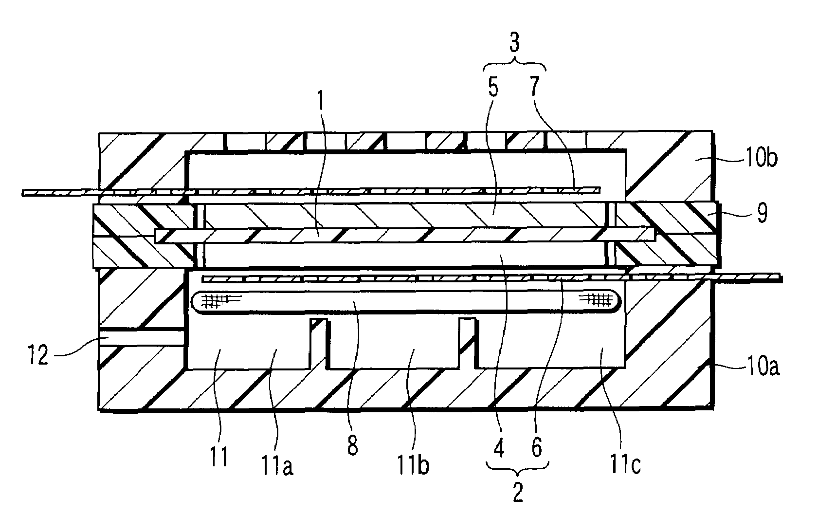
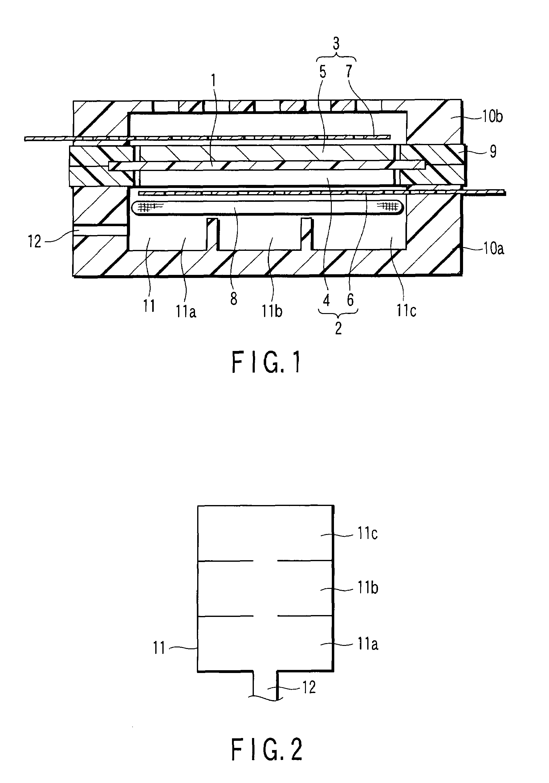
[0048]FIG. 1 (sectional view) shows a fuel cell according to an embodiment of the invention. In the figure, reference number 1 denotes a solid electrolyte membrane, reference number 2 a fuel electrode, reference number 3 an air electrode, and reference number 11 a fuel tank.

[0049]A membrane electrode assembly (MEA) as an electromotive section comprises a solid electrolyte membrane 1, and a fuel electrode 2 (anode) and air electrode 3 (cathode) stacked on both sides of the membrane. The fuel electrode 2 includes an anode catalyst layer 4 and fuel electrode collector 6. The air electrode 3 includes a cathode catalyst layer 5 and air electrode collector 7.

[0050]The anode and cathode catalyst layers 4 and 5 are formed of carbon paper coated with a catalyst. The catalyst-coated surface of the carbon paper is thermocompression-bonded to the solid electrolyte membrane 1. The catalyst layers are obtained, for example, as follows: A perfluorocarbon sulfonic acid solution serving as a proton ...


PUM

PropertyMeasurementUnit
heightaaaaaaaaaa
lengthaaaaaaaaaa
lengthaaaaaaaaaa

Abstract

An electrode membrane structure includes a solid electrolyte membrane of a polymer material, and a fuel electrode and an air electrode stacked on both sides of the solid electrolyte membrane. The fuel electrode is formed of an anode catalyst layer and a fuel electrode collector, and the air electrode is formed of a cathode catalyst layer and an air electrode collector. At the backside of the fuel electrode collector, a fuel tank is defined between a casing and a fuel holding film. The interior of the fuel tank is divided into a plurality of divisions by a partition to uniformly distribute liquid fuel to the fuel electrode. The liquid fuel (methanol) in the fuel tank is absorbed and held by the fuel holding film, is dispersed through the fuel holding film to the fuel electrode.

Description

CROSS REFERENCE TO RELATED APPLICATIONS[0001]This is a Continuation Application of PCT Application No. PCT / JP2006 / 300182, filed Jan. 11, 2006, which was published under PCT Article 21(2) in Japanese.[0002]This application is based upon and claims the benefit of priority from prior Japanese Patent Applications No. 2005-004176, filed Jan. 11, 2005; and No. 2005-004177, filed Jan. 11, 2005, the entire contents of both of which are incorporated herein by reference.BACKGROUND OF THE INVENTION[0003]1. Field of the Invention[0004]The present invention relates to a fuel cell for generating electricity utilizing hydrogen ions that are separated from liquid fuel at a fuel electrode using a catalyst, and more particularly to a fuel cell that does not use positive transfer means, such as a pump for supplying liquid fuel to a fuel electrode.[0005]2. Description of the Related Art[0006]In recent years, various attempts to use fuel cells as power supplies for various portable electronic devices, s...

Claims


Application Information

Patent Timeline
Patent Type & Authority Applications(United States)
IPC IPC(8): H01M8/10
CPCH01M8/04201H01M8/04208Y02E60/523H01M8/246H01M8/1011Y02E60/50H01M8/04H01M8/0263H01M8/24
Inventor SHIMOYAMADA, TAKASHINEGISHI, NOBUYASUKAN, HIROFUMI
Owner KK TOSHIBA
Why Eureka
Try Eureka