Closed end slotted carbon anodes for aluminum electrolysis cells

a technology of aluminum electrolysis cell and closed-end slotted carbon anodes, which is applied in the direction of chemistry apparatus and processes, separation processes, and dispersed particle separation, can solve the problems of increasing “pot” voltage and increasing “pot” noise, and achieves the effects of fast movement of gas bubbles, slow dissolution, and increased efficiencies

Active Publication Date: 2007-06-07
ARCONIC INC
View PDF8 Cites 6 Cited by
  • Summary
  • Abstract
  • Description
  • Claims
  • Application Information

AI Technical Summary

Benefits of technology

[0013] The non-continuous slot(s) are formed in the carbon anodes in such a manner as to direct flow of bubbles and coalesced bubbles generated on the anode surfaces into the slot(s) to facilitate the gas bubbles rapidly moving to the centerline of the reduction cell to expedite the dissolution of alumina, including alumina fines that typically float on top of the bath and are slow to dissolve. Facilitating the gas flow toward the center of the reduction cell keeps the metal to bath interface more stable increasing efficiencies, and results in less erosion to the reduction cell sidewall, thus increasing cell life. In a “Pot,” current flow is from the anode, through the low resistant liquid bath to the cathode. If a lot of gas bubbles are generated in the bath which bubbles cannot carry current, you are adding resistance to current flow through the bath, increased “Pot” voltage, and increased “Pot” noise. With slotted anodes the gas bubbles go into the slot(s) and vent in the center of the “Pot” between the anodes, which increases mixing in the alumina feeder area. Use of one or more slots keep the gas bubbles out of the bath that carries current from the anode to the cathode, reducing resistance to current flow, and reducing pot voltage, and pot noise.

Problems solved by technology

If a lot of gas bubbles are generated in the bath which bubbles cannot carry current, you are adding resistance to current flow through the bath, increased “Pot” voltage, and increased “Pot” noise.

Method used


Image

  • Closed end slotted carbon anodes for aluminum electrolysis cells
  • Closed end slotted carbon anodes for aluminum electrolysis cells
  • Closed end slotted carbon anodes for aluminum electrolysis cells

Examples


example

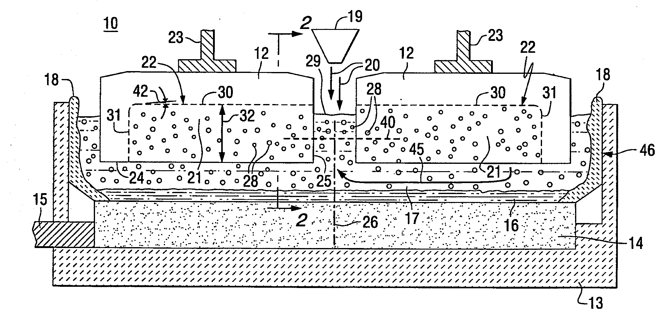
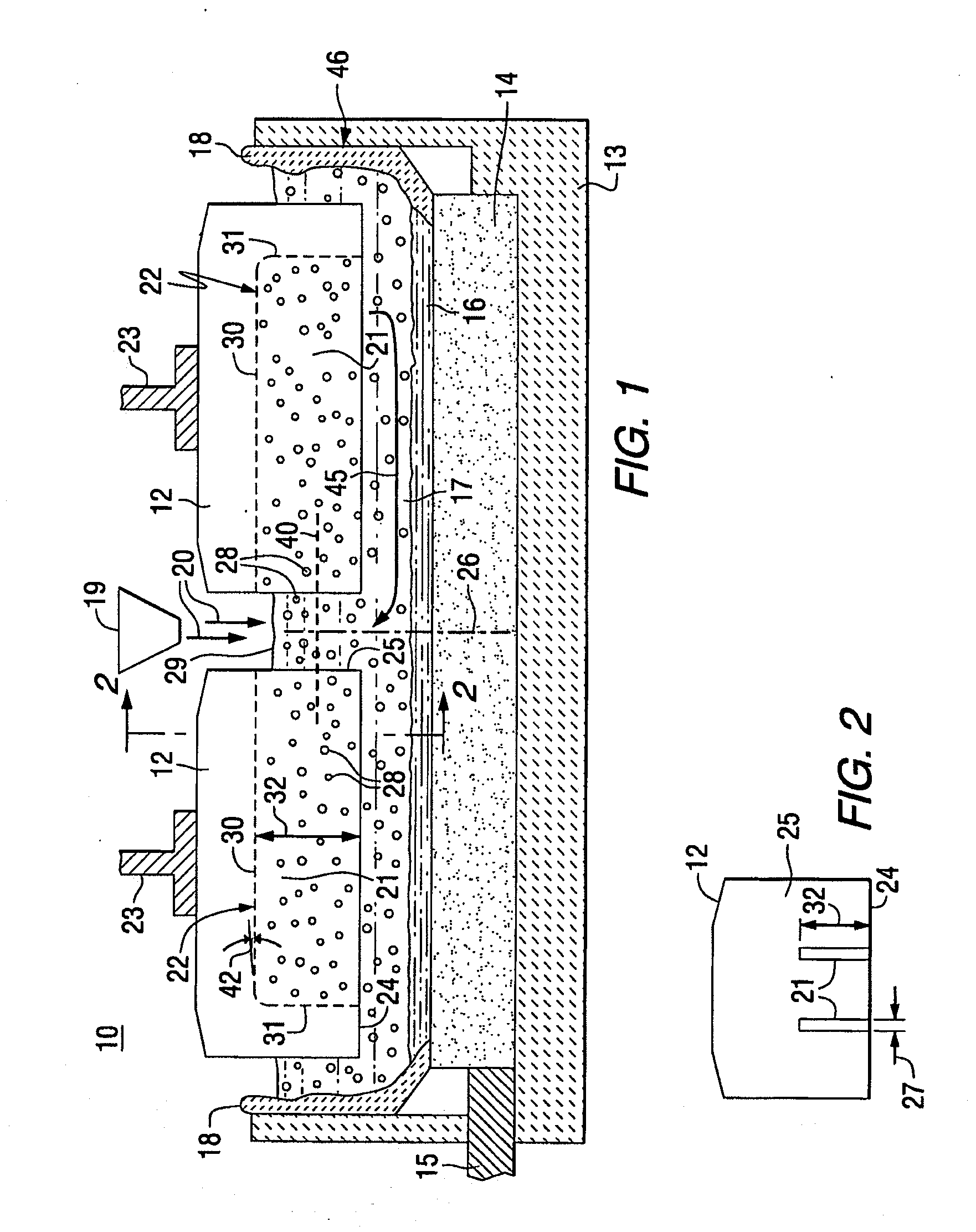
[0022] Experimental carbon anodes were produced with two 12 mm wide slots, each slot having a slot height from 45% to 80% of the anode thickness, with a flat roof portion, and a closed end. The front profile was similar to FIG. 2, where the slots were located near and on opposite sides of center, rather than at the near the sides.

[0023] From 16 to 32 anodes, two in a row, were placed in a pilot aluminum electrolysis cell, contacting molten cryolite at about 950° C. and operated with the slotted side surface facing the center of the cell, as shown in FIG. 1 with a pot voltage of about 402 volts to 4.7 volts. The use of the dual end closed slots generated substantial upward velocity of the various sized and shaped bubbles and was very helpful in breakup of alumina feed agglomerates and also lowered cell voltage by reducing anode gas bubble voltage.

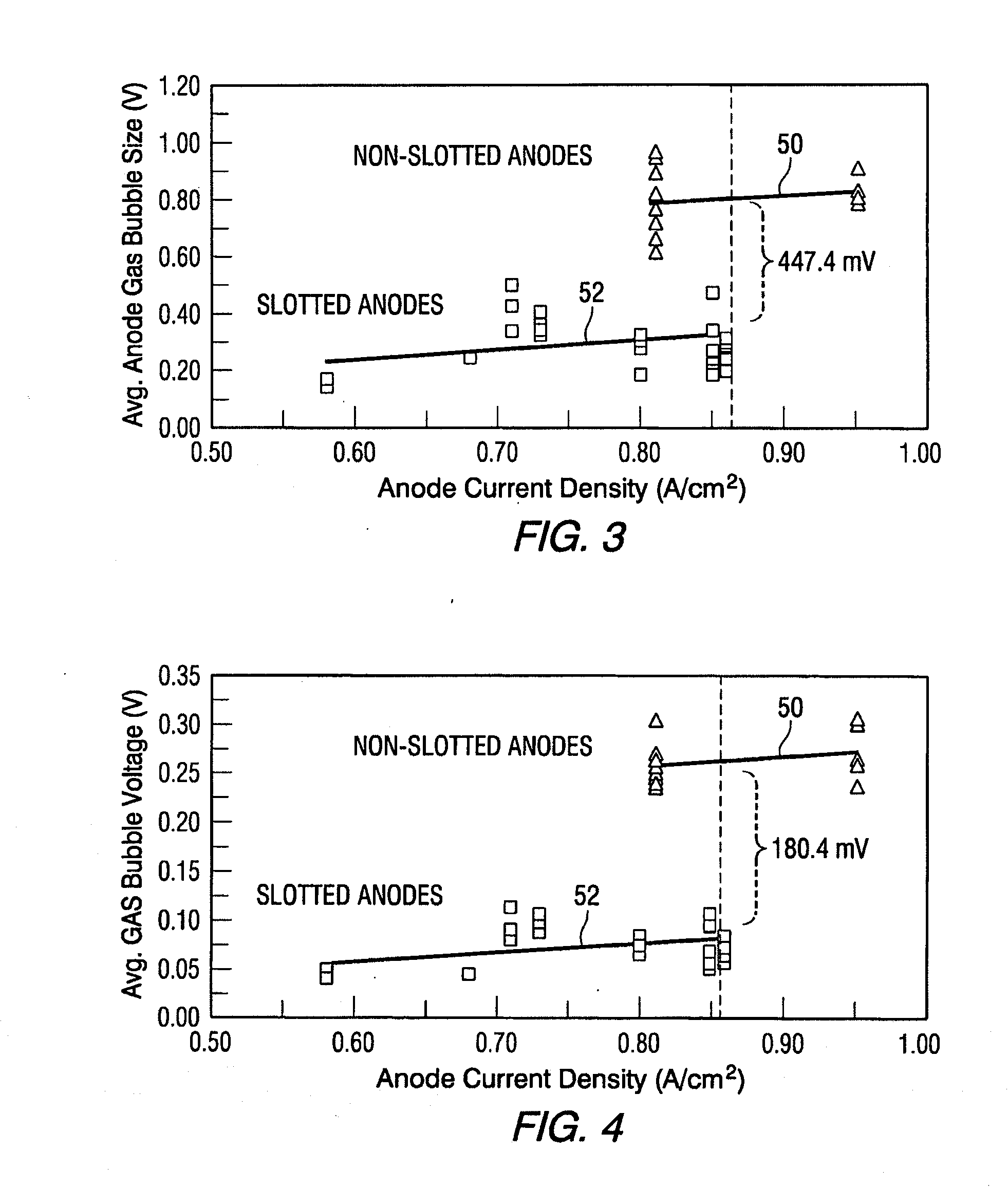
[0024] The presence of slots substantially reduced the magnitude of the anode voltage oscillation / fluctuation. FIG. 3 summarizes the magn...


PUM

PropertyMeasurementUnit
widthaaaaaaaaaa
widthaaaaaaaaaa
temperaturesaaaaaaaaaa

Abstract

An electrolysis cell (10) contains a number of carbon anodes (12) having top, bottom and side surfaces, operating in molten electrolyte (17) in an aluminum electrolysis cell (10), where gas bubbles (28) are generated at the anode surfaces and where alumina particles (20) are added to the top of the molten electrolyte, where the carbon anodes (12) have one inward slot (21) passing through the carbon anode (12) along the longitudinal axis 40 of the carbon anode and also passing through only one front surface (25) of the carbon anode, where the height (32) of the slot (21) is from about 45% to 80% of the anodes thickness and the slotted front surfaces (25) are disposed toward the center of the electrolysis cell so that generated gas bubbles (28) are directed to the alumina particles.

Description

CROSS-REFERENCE TO RELATED APPLICATION(S) [0001] This application is a continuation-in-part of U.S. patent application Ser. No. 10 / 799,036 filed Mar. 11, 2004, entitled “Closed End Slotted Carbon Anodes for Aluminum Electrolysis Cells”, now U.S. Pat. No. ______, which is incorporated herein by reference in its entirety.FIELD OF THE INVENTION [0002] The present invention relates to improved slotted carbon anodes for use in aluminum electrolysis cells. BACKGROUND OF THE INVENTION [0003] Aluminum is produced conventionally by the electrolysis of alumina dissolved in cryolite-based (usually as NaF plus AlF3) molten electrolytes at temperatures between about 900° C. and 1000° C.; the process is known as the Hall-Heroult process. A Hall-Heroult reduction cell / “pot” typically comprises a steel shell having an insulating lining of refractory material, which in turn has a lining of carbon that contacts the molten constituents. Conductor bars connected to the negative pole of a direct current...

Claims


Application Information

Patent Timeline
Patent Type & Authority Applications(United States)
IPC IPC(8): C25C3/06B01D59/40C25C3/12
CPCC25C3/125
Inventor BARCLAY, RON D.TARCY, GARY P.HOSLER, ROBERT B.WANG, XIANGWENBRUGGEMAN, JAY N.
Owner ARCONIC INC
Why Eureka
Try Eureka