Communication System

a communication system and receiver technology, applied in the field of communication systems, can solve the problems of transmitter and receiver being unable to communicate with each other, deteriorating reception sensitivity, and being susceptible to interference radio waves around the receiver

Inactive Publication Date: 2008-05-29
SONY CORP
View PDF5 Cites 288 Cited by
  • Summary
  • Abstract
  • Description
  • Claims
  • Application Information

AI Technical Summary

Benefits of technology

[0016]It is desirable to provide an excellent communication system that can perform data communication without interference with other communication systems using an electrostatic field between information apparatuses.
[0017]It is also desirable to provide an excellent communication system that can realize bulk data transmission by electrostatic coupling using RF signals.

Problems solved by technology

However, since a transmitter emits a radio wave regardless of whether there is a communication partner, there is a problem in that the transmitter is likely to be a generation source of a radio wave interfering with a communication system near the transmitter.
Also, since an antenna of a receiver receives radio waves arriving from a distance, the receiver is susceptible to an interference radio wave around the receiver.
The interference radio wave causes the deterioration in reception sensitivity.
Also, the transmitter and the receiver may be unable to communicate with each other when directions of polarization of radio waves are orthogonal.
The RFID system of the past that uses an electrostatic field and an induction field has a low communication speed, because a low-frequency signal is used, and thus is unsuitable for bulk data transmission.
Also, since a propagation loss occurs according to the length of a propagation distance with respect to a wavelength, when an RF signal is propagated by electric field coupling, a problem of a propagation loss corresponding to an inter-electrode distance becomes conspicuous.
Accordingly, it is difficult for the transmitter and the receiver to communicate with each other in a long distance, and thus it is not convenient for the user.
Thus, the restriction is imposed on the degree of freedom of the layout in the design of the case.

Method used


Image

  • Communication System
  • Communication System
  • Communication System

Examples


Embodiment Construction

[0059]In the following, a detailed description will be given of an embodiment of the present invention with reference to the drawings.

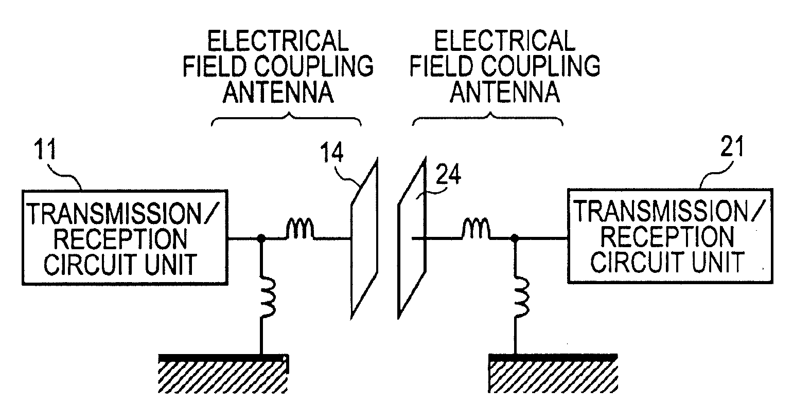
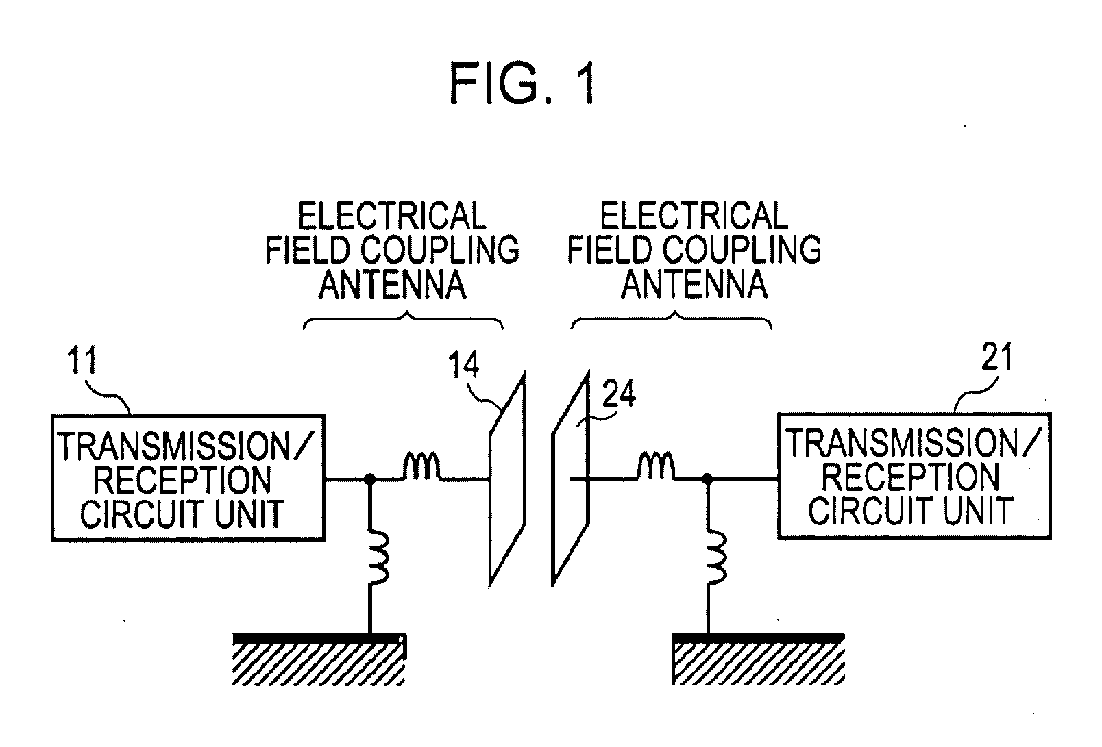
[0060]The present invention relates to a communication system that performs data transmission between information apparatuses using an electrostatic magnetic field. By a communication method based on electrostatic coupling, there is no coupling relation and a radio wave is not radiated when a communication partner is not present nearby. Thus, the communication system does not interfere with other communication systems. Even if a radio wave arrives from a distance, since an EFC antenna does not receive the radio wave, the communication system is not interfered by the other communication systems.

[0061]Also, in a radio communication using an antenna, the field intensity of a radiation electric field is inversely proportional to a distance. In contrast, the field intensity attenuates in inverse proportion to the square of a distance in the induction field...


PUM


Abstract

A communication system includes: a transmitter including a transmission circuit unit generating an RF signal for transmitting data and an electrical-field coupling antenna transmitting the RF signal as an electrostatic field or an induction field; a receiver including an electrical-field coupling antenna and a reception circuit unit subjecting an RF signal received by the electrical-field coupling antenna to reception processing; and a surface-wave propagation device including a plurality of linear surface-wave transmission lines for propagating a surface wave radiated from the electrical-field coupling antenna of the transmitter.

Description

CROSS REFERENCES TO RELATED APPLICATIONS[0001]The present invention contains subject matter related to Japanese Patent Application JP 2006-284870 filed in the Japanese Patent Office on Oct. 19, 2006, the entire contents of which are incorporated herein by reference.BACKGROUND OF THE INVENTION[0002]1. Field of the Invention[0003]The present invention relates to a communication system that performs bulk data communication between information apparatuses, and more particularly to a communication system that performs data communication without interference with other communication systems between information apparatuses using electrostatic magnetic field.[0004]More specifically, the present invention relates to a communication system that realizes bulk transmission by electric field coupling using radio-frequency (hereinafter referred to RF) signals, and more particularly to a communication system that extends a distance between electrodes of a transmitter and a receiver to be electrost...

Claims


Application Information

Patent Timeline
Patent Type & Authority Applications(United States)
IPC IPC(8): H04B5/00
CPCH04B5/0081
Inventor KONYA, SATOSHIWASHIRO, TAKANORI
Owner SONY CORP
Why Eureka
Try Eureka