Boiler

a boiler and heat exchanger technology, applied in the field of boilers, to achieve the effect of reducing nox and high durability

Active Publication Date: 2008-06-05
MIURA COMPANY LIMITED
View PDF11 Cites 6 Cited by
  • Summary
  • Abstract
  • Description
  • Claims
  • Application Information

AI Technical Summary

Benefits of technology

[0017]According to the present invention, it is possible to obtain a boiler equipped with a water tube group performing heat recovery effectively and having expansion heat

Problems solved by technology

When stud fins are used as the expansion heating surfaces, cracking, de

Method used


Image

  • Boiler
  • Boiler
  • Boiler

Examples


first embodiment

[0048]In the following, a boiler according to a second embodiment of the present invention will be described with reference to the drawings.

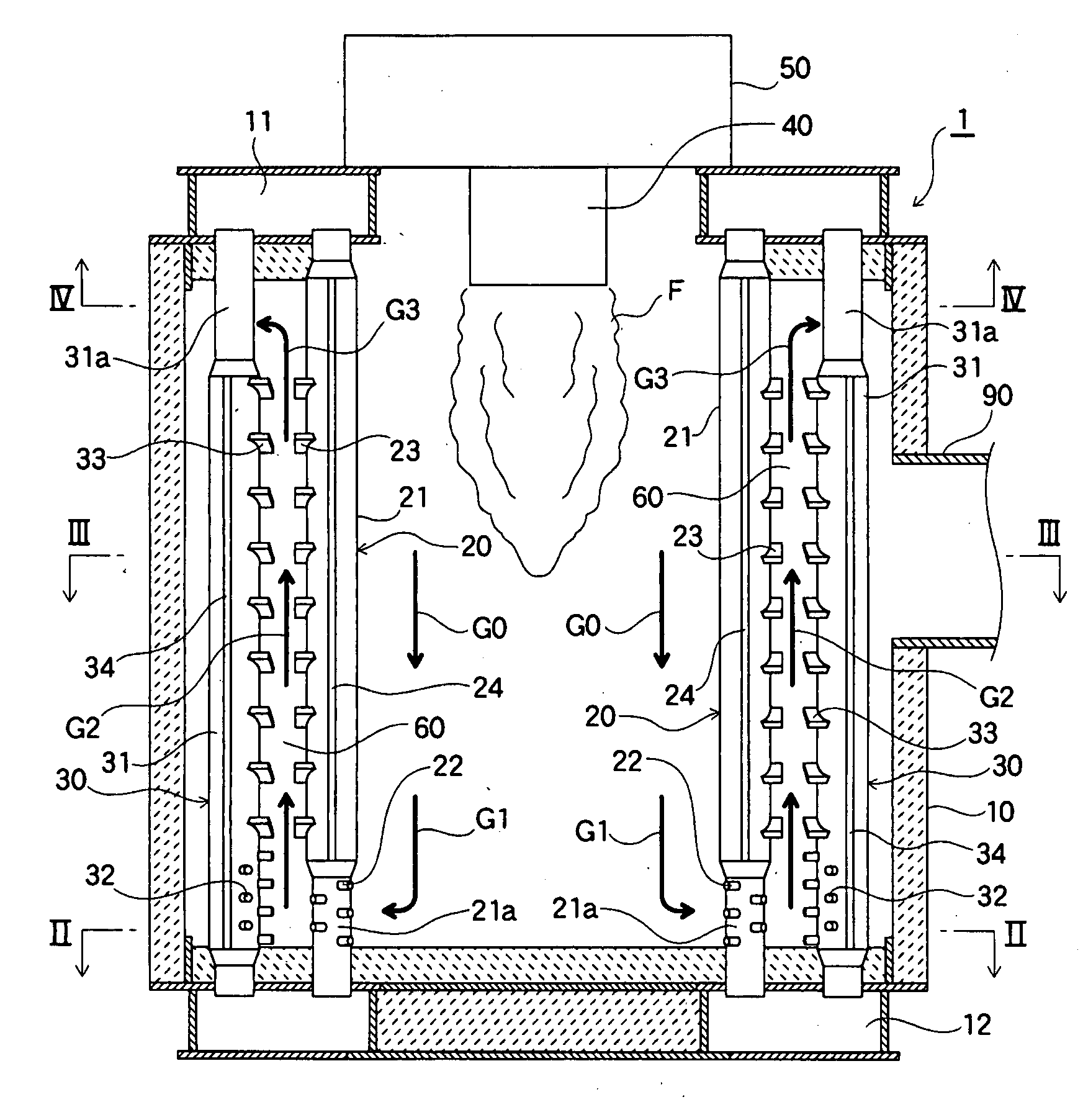
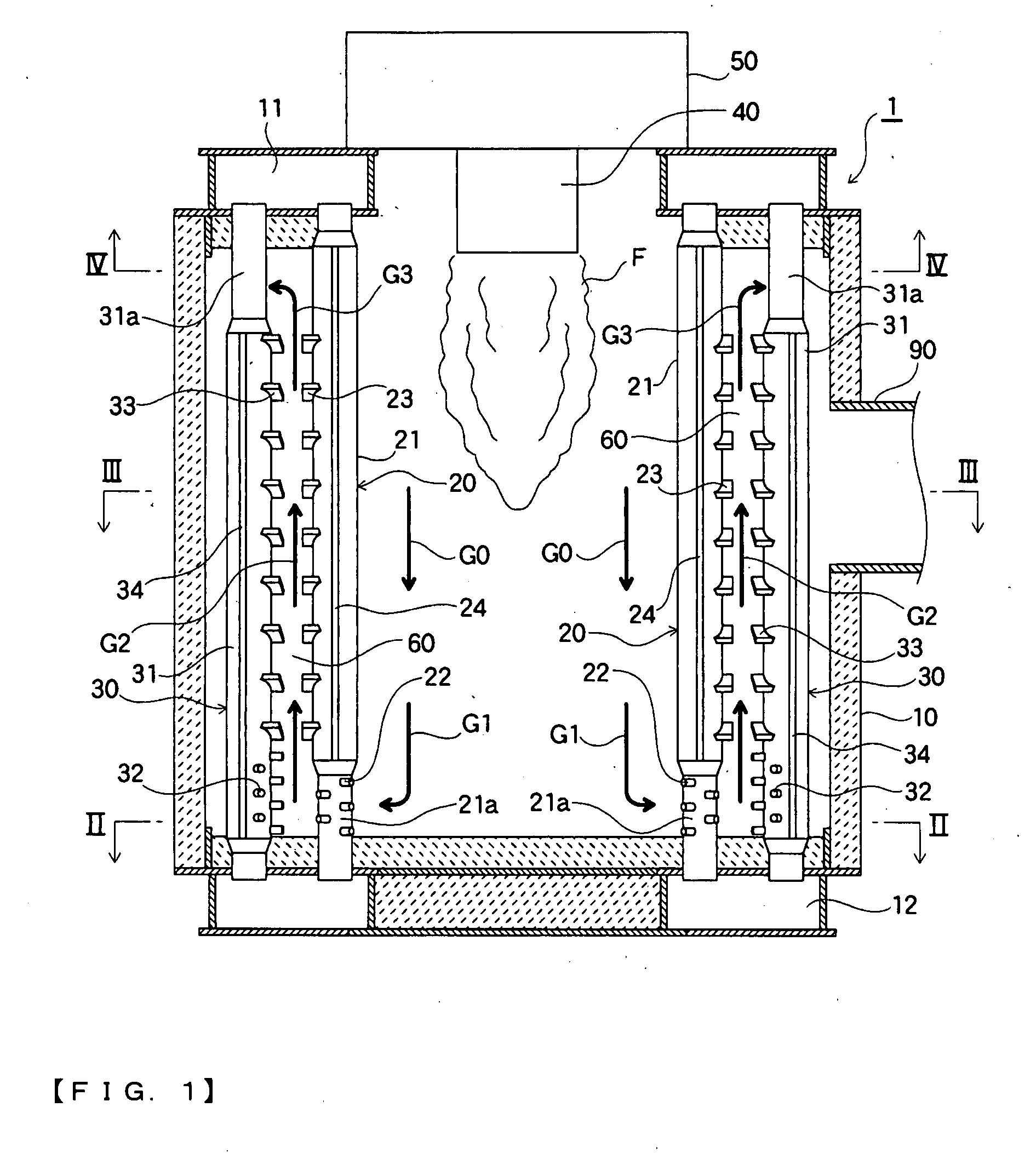
[0049]FIG. 1 is an explanatory longitudinal sectional view of a boiler according to the first embodiment of the present invention. FIG. 2 is a schematic explanatory cross-sectional view taken along the line II-II of FIG. 1. FIG. 3 is a schematic explanatory cross-sectional view taken along the line III-III of FIG. 1. FIG. 4 is a schematic explanatory cross-sectional view taken along the line IV-IV of FIG. 1.

[0050]As shown in FIG. 1, etc., a boiler 1 according to this embodiment is formed by using a boiler body 10 having water tube groups arranged in an annular fashion, and a burner 40 arranged at the center of the water tube groups; on top of the burner 40, there is provided a wind box 50 for supplying combustion air to the burner 40.

[0051]The boiler body 10 includes an upper header 11 and a lower header 12, between which a plurality of water tu...

second embodiment

[0072]Next, a boiler according to the second embodiment of the present invention will be described. The basic construction of the boiler of the second embodiment of the present invention is the same as that of the first embodiment described above. Thus, in the following, the portions that are the same as those of the first embodiment are indicated by the same reference numerals, and a detailed description thereof will be omitted, with the following description mainly centering on the difference in construction from the first embodiment.

[0073]FIG. 5 is a schematic explanatory cross-sectional view of the boiler of the second embodiment of the present invention. More specifically, it is a schematic explanatory view corresponding to FIG. 2 showing the first embodiment described above. That is, FIG. 5 is a schematic explanatory cross-sectional view of the portion of the boiler of this embodiment in the vicinity of the inner gas flow passages 25 (corresponding to the “gas flow passages” o...

third embodiment

[0080]Next, a boiler according to the third embodiment of the present invention will be described. The basic construction of the boiler of the third embodiment of the present invention is the same as that of the first embodiment described above. Thus, in the following, the portions that are the same as those of the first embodiment are indicated by the same reference numerals, and a detailed description thereof will be omitted, with the following description mainly centering on the difference in construction from the first embodiment.

[0081]FIG. 6 is an explanatory longitudinal sectional view of a boiler according to the third embodiment of the present invention. FIG. 7 is a schematic explanatory cross-sectional view taken along the line VII-VII of FIG. 6. FIG. 8 is a schematic explanatory cross-sectional view taken along the line VIII-VIII of FIG. 6. FIG. 9 is a schematic explanatory cross-sectional view taken along the line IX-IX of FIG. 6.

[0082]As shown in FIG. 6, etc., a boiler 1...


PUM


Abstract

To provide a boiler equipped with a water tube group performing heat recovery effectively and having expansion heating surfaces (fins or the like) of high durability, the present invention provides a boiler (1) including: a boiler body (10) having an inner water tube group (20) and an outer water tube group (30) that are arranged in an annular fashion; and a burner (40) arranged at a central portion of the inner water tube group (20), in which: intervals between adjacent inner water tubes constituting the inner water tube group (20) are closed except for portions where a gas flow passage is provided; and stud fins (22 and 32) are provided on a portion of at least one of the inner water tube group (20) and the outer water tube group (30) in a vicinity of the gas flow passage.

Description

BACKGROUND OF THE INVENTION[0001]1. Field of the Invention[0002]The present invention relates to a boiler (multi-tube once-through boiler).[0003]2. Description of the Related Art[0004]A boiler has conventionally been well known which is equipped with a boiler body having a water tube group arranged in an annular fashion. In such a boiler, a burner is generally arranged at the center of the water tube group. That is, in a boiler of this construction, the portion at the center of the water tube group arranged in an annular fashion functions as a combustion chamber for burning the fuel supplied from the burner.[0005]Further, regarding conventional boilers, in order to increase the amount of heat recovered from the combustion gas produced by the burner, a technique is known according to which predetermined water tubes constituting a water tube group are equipped with fins (see, for example, JP 02-75805 A).[0006]However, the above conventional boiler has a problem in that effective heat ...

Claims


Application Information

Patent Timeline
IPC IPC(8): F24H1/14
CPCF24H1/403F24H1/406F24H9/0026F28F2215/04F28D7/1669F28F1/124F28D7/0041F24H1/40
Inventor SUMI, SOJI
Owner MIURA COMPANY LIMITED
Why Eureka
Try Eureka