Ignition control device for internal combustion engine

Inactive Publication Date: 2008-06-05
DENSO CORP
View PDF2 Cites 34 Cited by
  • Summary
  • Abstract
  • Description
  • Claims
  • Application Information

AI Technical Summary

Benefits of technology

[0011]According to the above the ignition control device, the multi-spark period setting element can set the multi-spark period of the multi-spark operation based on the ignition timing signal. The multi-spark period setting element can recognize the multi-spark peri

Problems solved by technology

However, in advance of a time when the spark plug starts generating a spark, the ignition control device can not recognize an expected energy consumption or an energy density during the

Method used


Image

  • Ignition control device for internal combustion engine
  • Ignition control device for internal combustion engine
  • Ignition control device for internal combustion engine

Examples


first embodiment

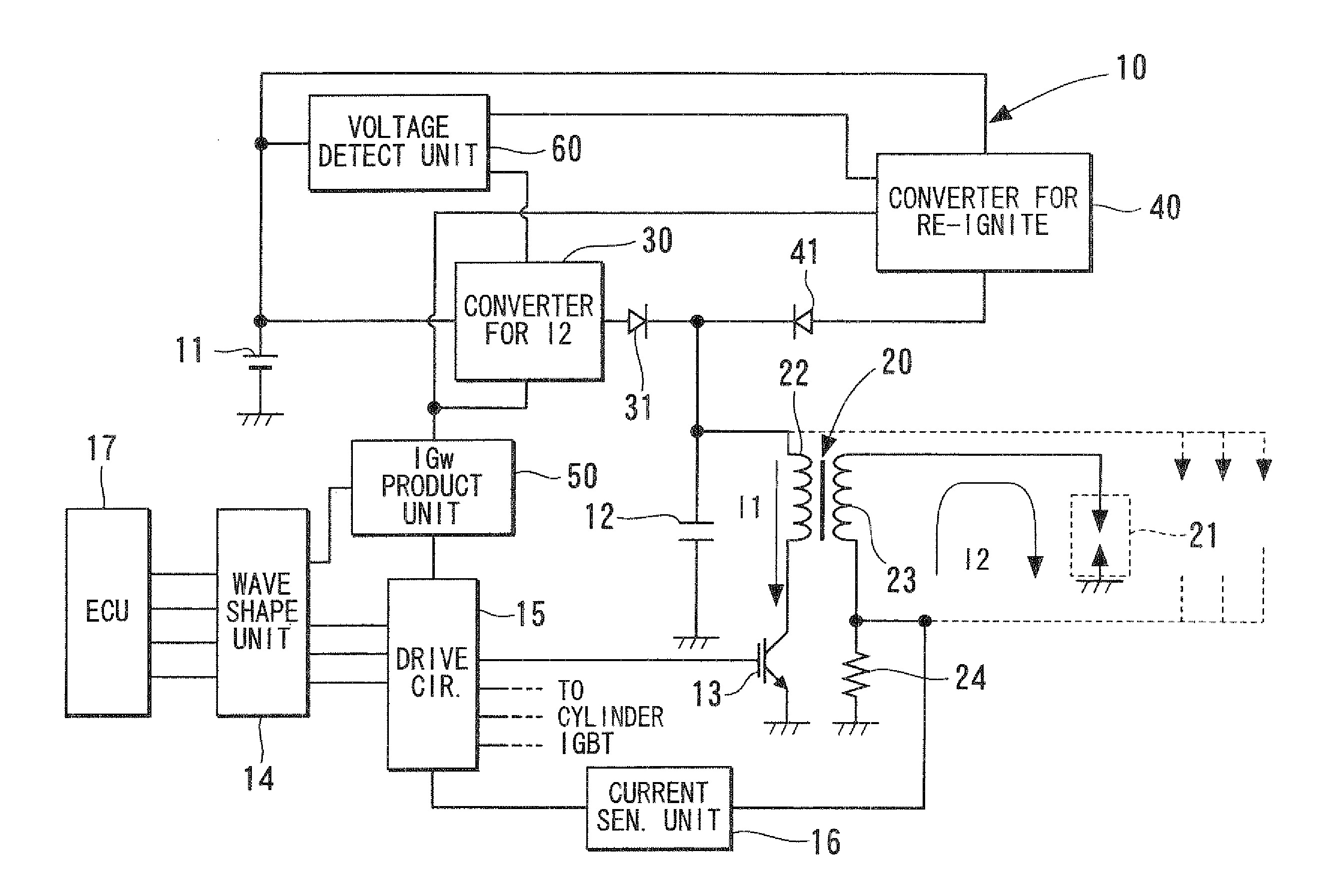
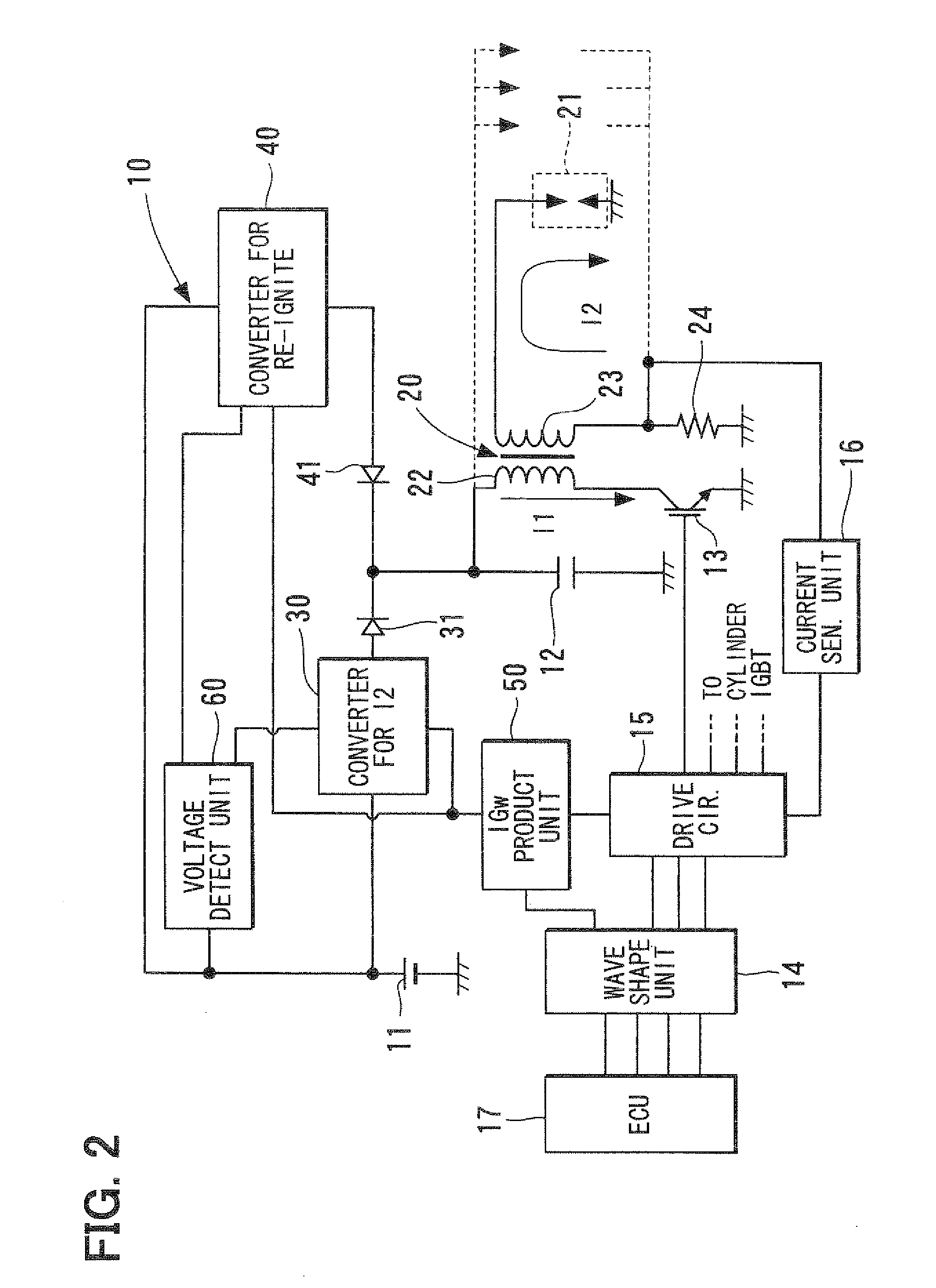
[0027]An ignition control device 10, for example as shown in FIG. 2, includes a DC power source such as a battery 11, a first electric energy generator such as a first DC / DC converter 30, a second electric energy generator such as a second DC / DC converter 40, an charging element such as a first capacitor 12, an ignition coil 20, a switching element such as an insulated gate bipolar transistor (IGBT) 13, a waveform shaping unit 14, an ignition control element such as a drive circuit 15, an ignition timing signal generator such as an IGw production unit 50, a supply voltage detection unit 60, and a current sensing unit 16. The ignition coil 20 is coupled with a spark plug 11. The ignition control device 10 is coupled with an ECU 17. The ignition control device 10 generates an ignition timing signal. When the ECU 17 commands the ignition, the spark plug 20 of the ignition control device 10 generates a spark.

[0028]The battery 11 is coupled with the first DC / DC converter 30 and the secon...

second embodiment

[0054]FIG. 11 shows an ignition control device according to a second embodiment of the present invention.

[0055]In the present embodiment, the ignition control device 10 includes an ignition state detection unit such as an IGf signal generation unit 70, as shown in FIG. 11. The IGf signal generation unit 70 outputs a signal IGf that is used as a basis for determining whether the spark plug 21 discharges abnormally. The abnormal discharging of the spark plug 21 is caused by, for example, abnormal behavior of the first DC / DC converter 30 and the second DC / DC converter 40. The IGf signal generation unit 70 includes a signal generator circuit 71 having a secondary current switching element 72, as shown in FIG. 12. The secondary current switching element 72 generates a negative spark signal, as shown in FIG. 13. The negative spark signal is generated when the direction of a current flow at the secondary coil 23 of the ignition coil 20 is negative. As shown in FIG. 13, the charging of a fo...


PUM


Abstract

An ignition control device for controlling a multi-spark operation comprises: a secondary electric energy generator generating an electric energy to reignite an air fuel-mixture associated with an internal combustion engine during the multi-spark operation; a switching element capable of controlling the supplying of the electric energy to a primary coil of an ignition coil, the controlling causing a secondary current in a secondary coil of the ignition coil; an ignition timing signal generator generating an ignition timing signal based on a driving state of the engine; a multi-spark period setting element setting a multi-spark period of the multi-spark operation based on the ignition timing signal; and an ignition control element setting an amount of electric power supplied to the secondary electric energy generator based on the multi-spark period before the performing of the multi-spark operation is started, and for controlling the switching element.

Description

CROSS REFERENCE TO RELATED APPLICATION[0001]The present application is based on and claims priority to Japanese Patent Application No. 2006-328069 filed on Dec. 5, 2006, the disclosure of which is incorporated herein by reference.FIELD OF THE INVENTION[0002]The present invention relates to an ignition control device for an internal combustion engine. More specifically, the present invention relates to an ignition control device for performing an ignition using a multi-spark operation during every combustion stroke.BACKGROUND OF THE INVENTION[0003]An ignition device typically includes a spark plug, for example, in the case of a spark-ignition internal combustion engine. The spark plug ignites an air-fuel mixture by means of an electrical spark. A multi-spark method of igniting the air-fuel mixture has been proposed in recent years, in which the ignition device ignites the air-fuel mixture by means of a multi-spark operation for every combustion stroke in order to improve a combustion...

Claims


Application Information

Patent Timeline
IPC IPC(8): F02P5/145
CPCF02P15/08F02P3/053F02P9/007
Inventor TORIYAMA, MAKOTOYAMAUCHI, YUHKI
Owner DENSO CORP
Why Eureka
Try Eureka