
Apparatus and system for reducing mechanical ventilator noise

a technology of mechanical ventilator and apparatus, which is applied in the direction of mechanical apparatus, valves, respirators, etc., can solve the problems of reducing the patient's communication ability, affecting the patient's ability to eat, and affecting the patient's ability to communica

Inactive Publication Date: 2008-06-05
GENERAL ELECTRIC CO
View PDF1 Cites 79 Cited by
  • Summary
  • Abstract
  • Description
  • Claims
  • Application Information

AI Technical Summary

Benefits of technology

"The present patent is about a device and system for reducing the noise that patients receive while using a mechanical ventilator and pneumatic helmet patient interface. The device includes a sound dampening apparatus that has an inlet, outlet, and a sound absorbent material inside it. The sound dampening apparatus can be connected to a medical gas source and patient interface through pneumatic conduits. The technical effect of this invention is to provide a quieter and more comfortable respiratory support for patients."

Problems solved by technology

A drawback of patient interfaces that utilize a face mask is that the patient's mouth is blocked.
This reduces the patient's ability to communicate.
Furthermore a face mask makes it difficult for the patient to ingest nutrition and / or medication.
Also, in the event that a patient vomits, a face mask presents an increased risk of a blocked airway.
Finally, patients find discomfort with the use of a mask, both due to the blockage of the patient's mouth as well as the pneumatic pressure that is applied to the patient's face through the patient interface.
However, it has been identified that the noise within the confined space of a non-invasive ventilation helmet can reach discomforting and even dangerous levels.
While OSHA workplace safety standards suggest limiting exposure to noises above 100 dB to less than 2 hours at a time, the patient may be exposed to these noise levels throughout the duration of the respiratory support, which may last days or weeks.
The loud noises also contribute to the discomfort that the patient associates with receiving respiratory support.
Patient discomfort can lead to an overall unfavorable care experience, and can lead to adverse physiological effects such as increased heart rate or blood pressure.
Furthermore excessive noise in the helmet may prevent the patient from falling asleep, and / or staying asleep, thereby reducing the patient's ability to recuperate.
The noise within the helmet has many sources within the mechanical ventilator.
One source of noise is the medical gas supply source.
This compressor or pump is typically loud in its operation, resulting in this noise being transmitted to the helmet.
Secondly, the flow of medical gas may be received by the mechanical ventilator from a wall supply of high pressure medical gas supplied to the hospital room.
Therefore, both sources of medical gas commonly used by medical ventilators cause noise in the NIV helmet.
However, the noise within the patient interface is also an issue with these sources of medical gas flow.
However, the corrugated tubing causes turbulence in the flow of medical gas, therefore creating additional noise in the breathing circuit and the NIV helmet.
However, this technique has not shown a meaningful effect on reducing the noise within the helmet.
However, this too did not produce a meaningful decrease in the noise experienced inside of the helmet.
The lack of effectiveness of these attempts to reduce noise may be due to the fact that the noise is the result of inherent features of standard mechanical ventilator components.
Furthermore, the HME filter is not designed to maximize any sound-attenuating properties that the HME filter may have.
While a HME filter comprises a core of foam or other filter material that the medical gas must flow through, the amount of material present is not sufficient to dampen the noise effectively.
Increased resistance within the breathing circuit of a mechanical ventilation system is undesirable as this resistance must be overcome by higher pressures within the breathing circuit and the resistance affects the waveform of medical gas that is actually received by the patient.

Method used


Image

  • Apparatus and system for reducing mechanical ventilator noise
  • Apparatus and system for reducing mechanical ventilator noise
  • Apparatus and system for reducing mechanical ventilator noise

Examples


Embodiment Construction

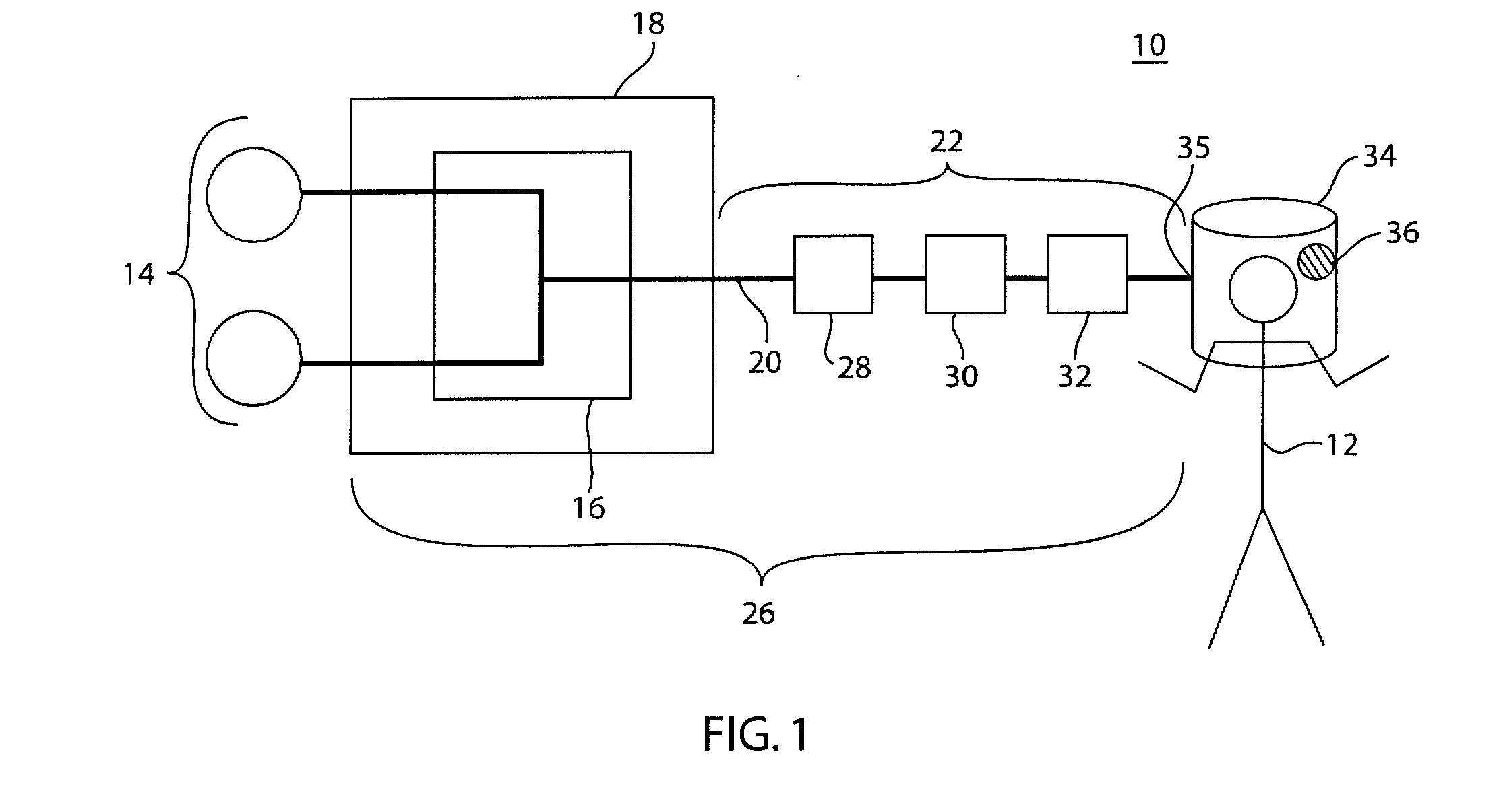
[0019]FIG. 1 depicts a schematic diagram of a mechanical ventilation system 10 for providing respiratory support to a patient 12. The system 10 comprises a series of pneumatic conduits and modules 26 that form a pneumatic connection between a medical gas source 14 and the patient 12. The medical gas source 14 is connected to a manifold 16 of a mechanical ventilator 18. The manifold 16 serves to combine the constituent gases that are provided from the medical gas source 14 into the desired medical gas that is to be delivered to the patient 12. Alternatively, the mechanical ventilator 18 may be replaced by an alternative device for controlling the flow of medical gas. This alternative device may comprise a CPAP device connected to the source of medical gas or a manually operated ventilation bag.

[0020]The term “medical gas” as used in this application refers to any gas or combination of gases that is delivered to a patient in a clinical setting. Most commonly, the medical gas delivered...


PUM


Abstract

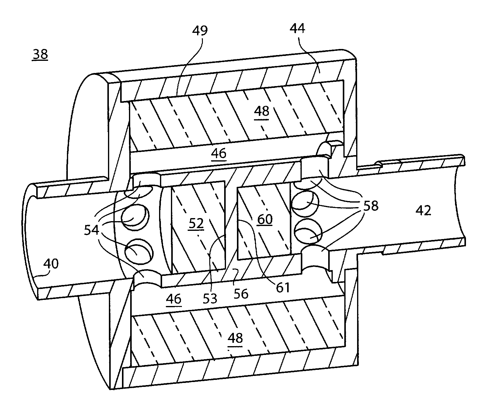
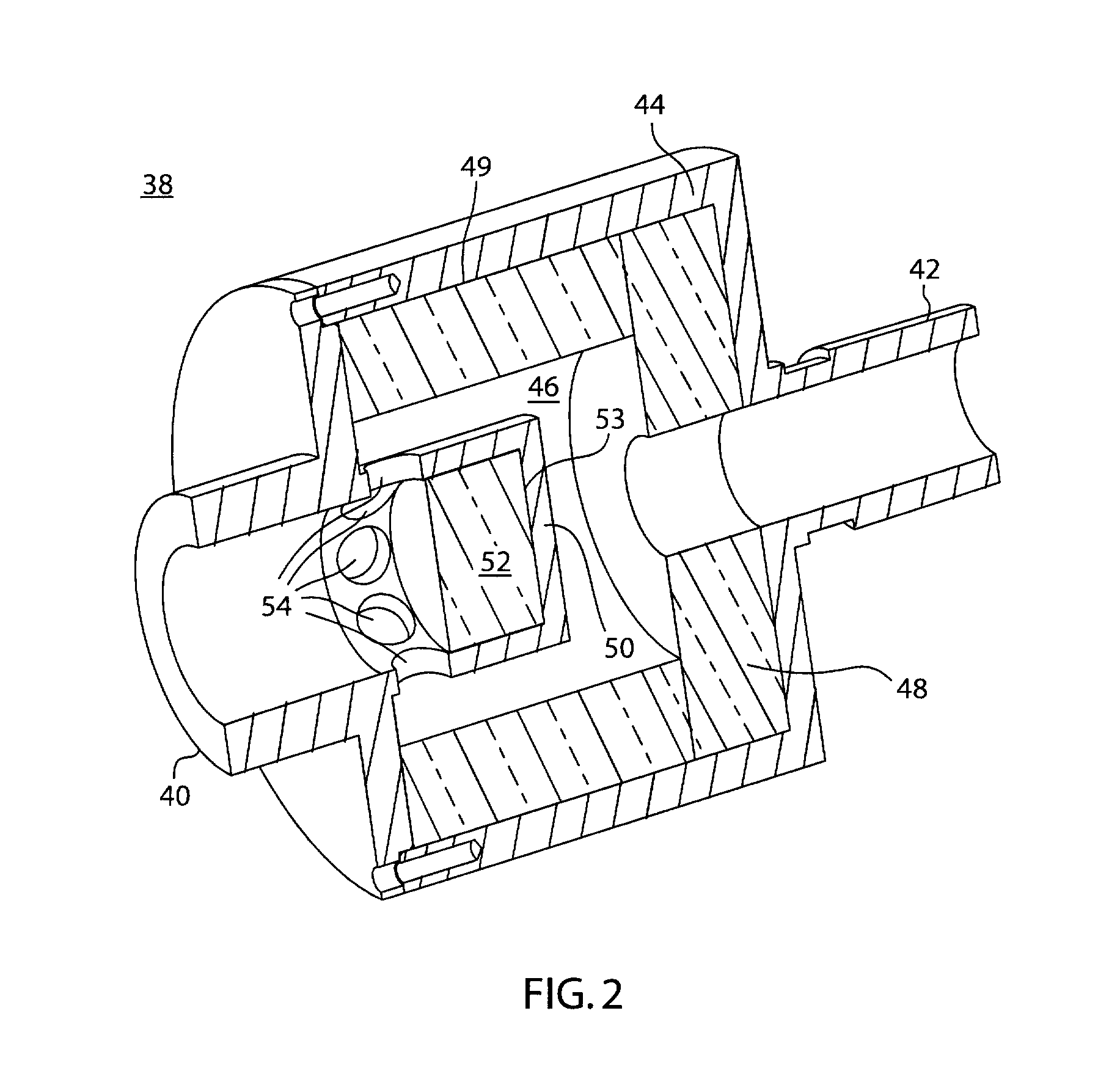
A sound dampening apparatus to be disposed in pneumatic connection with a respiratory support system. The respiratory support system may comprise a source of medical gas, a plurality of pneumatic connections and a patient interface. The sound dampening apparatus comprises an inlet, an outlet, and an outer case which forms a sound dampening chamber. As the medical gas flows through the sound dampening apparatus, the noise energy associated with the flow of medical gas is reduced.

Description

FIELD OF THE DISCLOSURE[0001]The present disclosure relates to mechanical ventilation systems for the provision of respiratory support to a patient. More specifically, the present disclosure relates to a device and system for reducing the noise generated by the mechanical ventilator that is experienced by the patient.BACKGROUND OF THE DISCLOSURE[0002]The application of non-invasive ventilation (“NIV”) to a patient in need of respiratory support provides the patient with benefits over the use of invasive ventilation techniques such as with an endotracheal (ET) tube. NIV reduces the trauma that a patient experiences in the application of invasive ventilation techniques, for example, intubation. The use of NIV also reduces the risk of ventilator-associated pneumonia and facilitates the weaning of a patient off of mechanical ventilation. Many types of patient interfaces exist to provide a patient with non-invasive ventilation, the most common interfaces utilize a version of a face mask....

Claims


Application Information

Patent Timeline
Patent Type & Authority Applications(United States)
IPC IPC(8): A61M16/00
CPCA61M16/08A61M16/0627A61M2205/42A61M16/0816
Inventor ACKER, JARON M.BILEK, KRISTOPHER J.PINKERT, JOHN R.THAM, ROBERT Q.
Owner GENERAL ELECTRIC CO
Learn More