
Process of and device for induction-hardening helical springs

Inactive Publication Date: 2008-06-05
MUHR UND BENNDER KG
View PDF0 Cites 14 Cited by
  • Summary
  • Abstract
  • Description
  • Claims
  • Application Information

AI Technical Summary

Benefits of technology

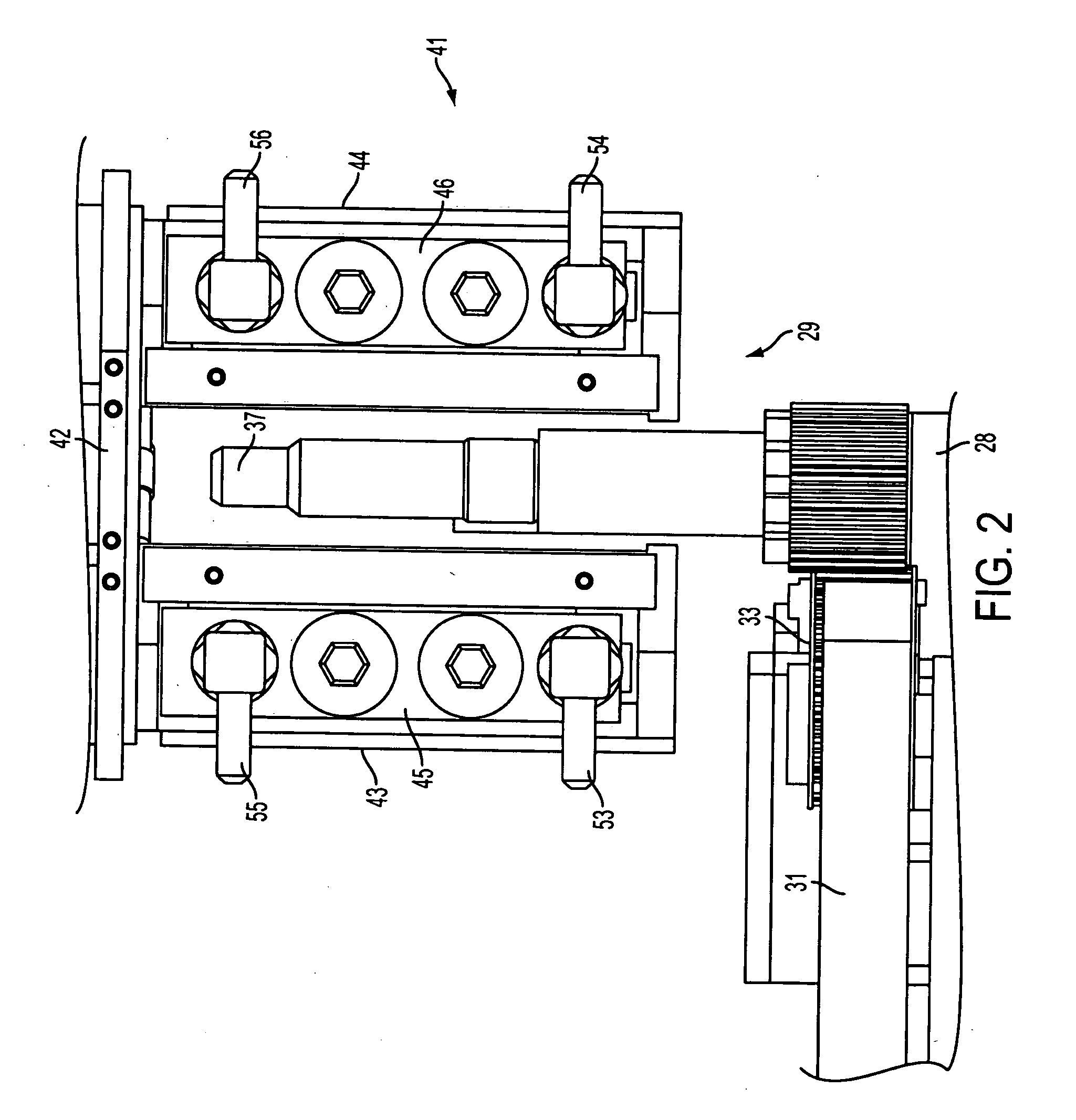
[0018]An important feature of the guidance of the helical springs is an inductor assembly which can be provided having a U-shape in a cross-section extending perpendicularly to the part of movement of the helical springs, i.e. more particularly in a horizontal section. In addition, the mandrels of the holding devices can extend between the two open legs of the “U”, preferably disposed equidistant between the two legs. It is preferable to provide a sufficient distance between the inductor assembly and the mandrels and holding devices, which can both comprise a non-conducting material or insulating material, thereby reducing any interfering factors which may adversely affect the required alternating field. It is preferable to provide that the helical springs rotate uniformly and rapidly, on their path through the alternating field whereby uniform heating on all surfaces and through-heating can be provided.

Problems solved by technology

In the case of components in the form of helical springs, more particularly valve springs, it is difficult to reliably cover the entire material surface by induction-heating.

Method used


Image

  • Process of and device for induction-hardening helical springs
  • Process of and device for induction-hardening helical springs
  • Process of and device for induction-hardening helical springs

Examples


Embodiment Construction

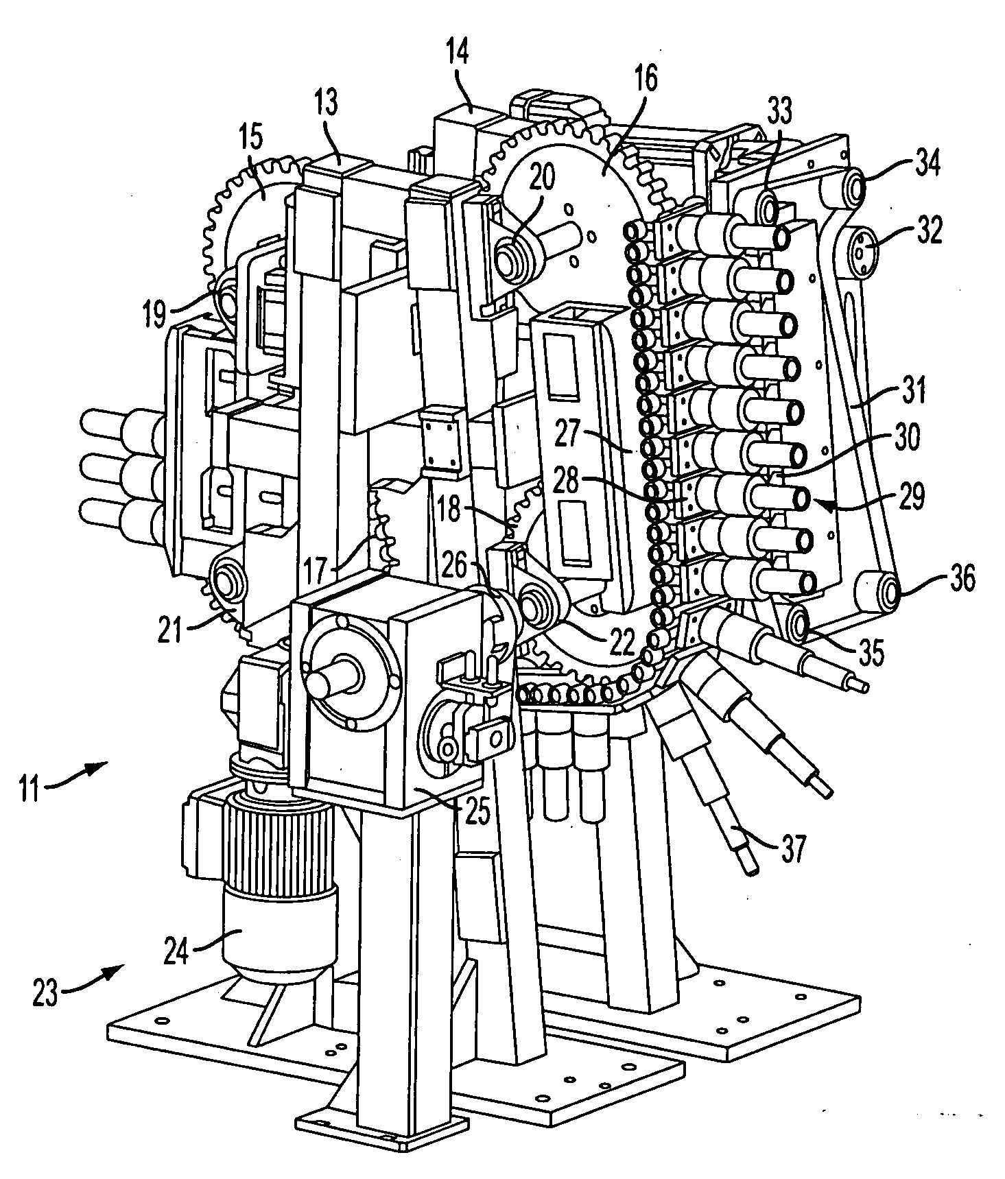
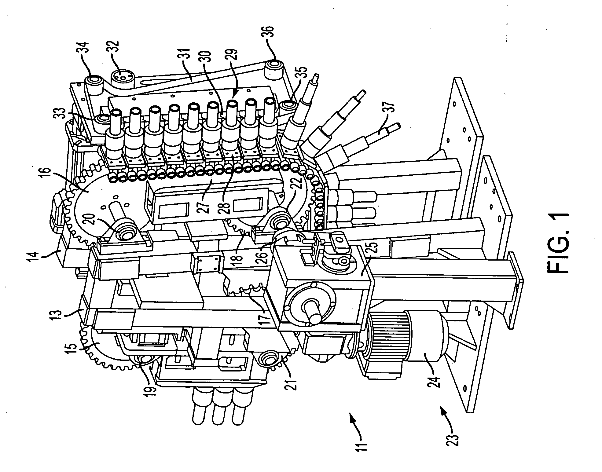
[0024]FIG. 1 shows a machine frame 11 with two stands 13, 14 between which member belt guiding means are arranged including four chain gears 15, 16, 17, 18. In each case, bearing blocks 19, 20, 21, 22 of the chain gears are provided in the front stand 13. In front of the front stand 13, a drive assembly 23 with a motor 24 is provided. In addition, a transmission 25 is provided whose output shaft, via a clutch 26, acts on the axle of the chain gear 18. Across the four chain gears, an infinite member chain 27 is provided including at least a front vertical part and a lower part deflected into the horizontal plane. The member chain 27 comprises individual chain members 28 in the shape of a rectangular plate on which centrally rotatably supported holding devices 29 are positioned whose axes of rotation are positioned normally relative to the plane of the chain members 28. In addition, it can be appreciated that a suitable rolling contact or friction bearing between a part connected to t...


PUM

PropertyMeasurementUnit
Temperatureaaaaaaaaaa
Poweraaaaaaaaaa

Abstract

A process of induction-heating helical springs, more particularly valve springs, for the purpose of carrying out subsequent hardening by quenching and tempering, wherein the helical springs, while being individually fixed and rotatingly driven, are guided through an electro-magnetic alternating field.

Description

FIELD OF THE INVENTION[0001]The invention relates to a process of and device for induction-heating helical springs, more particularly valve springs, for the purpose of carrying out subsequent hardening by quenching and subsequent tempering by renewed heating, generally referred to as quenching and tempering.BACKGROUND OF THE INVENTION[0002]In the case of induction heating components consisting of iron for the purpose of carrying out subsequent hardening by quenching, an electro-magnetic alternating field ensures rapid reproducible heating to 850 to 1000° C. in order to produce austenite (γ-iron). If subsequently cooled rapidly to a temperature below 250° C., the γ-iron is converted into martensite, i.e. the carbon atoms are finely distributed and fixed in the resulting α-iron. The conversion of the iron, i.e. the hardening process, also depends on the cooling speed. As a rule, hardening is followed by a renewed heating and temperature-holding process, i.e. tempering at tempering tem...

Claims


Application Information

Patent Timeline
IPC IPC(8): C21D9/02C21D1/18H05B6/10C21D1/42
CPCC21D9/02C21D1/10Y02P10/25
Inventor HUFNAGEL, THORSTENBONSE, RUDOLF
Owner MUHR UND BENNDER KG
Learn More