Suspension system for a cordless window covering

a suspension system and window covering technology, applied in door/window protective devices, building components, constructions, etc., can solve the problems of pulling cords, increasing the weight of suspension cords, and lessening the aesthetic appearance of window coverings, etc., to achieve the effect of higher static friction

Active Publication Date: 2008-06-05
TEH YOR CO LTD
View PDF39 Cites 37 Cited by
  • Summary
  • Abstract
  • Description
  • Claims
  • Application Information

AI Technical Summary

Benefits of technology

[0014]The amount of friction can be adjusted depending on the weight of the window cover member and the cord texture and thickness by configuring the friction member, such as the hook member, to cause the suspension member to travel a path that includes a plurality of turns. The distances between turns, the angles of the turns, and the amount of contact between the friction member and the cord can all be adjusted to provide the desired amount of static friction suitable for a particular application. A higher static friction allows the same control module to be used over a greater range of window covering lengths.
[0015]The hook may also be a reaction member designed to prevent undesired movement of the bottom rail and ensure a stationary position (e.g., no movement between the cord and the hook). A reaction force exerted by the hook on the cord, or other offset surfaces, contributes to counteract the force of the spring to keep stationary the cord when the bottom rail is positioned at the desired height.

Problems solved by technology

One shortcoming of such pull cords is that they require peripheral members that distract from the window cover material and can lessen the aesthetic appearance of the window covering.
In addition, pull cords also present a potentially dangerous situation in that they are of relatively long lengths and may be mishandled by certain persons, especially children, such that accidental choking or hanging may occur.
One issue that has been presented in other so-called cordless window coverings is that as a window covering is raised, increasing amounts of the window cover material are gathered and supported on the bottom rail, thereby increasing the weight suspended by the suspension cord.
One shortcoming of the previous attempts, however, is the complexity of the designs in that a substantial number of interconnected parts are required.

Method used


Image

  • Suspension system for a cordless window covering
  • Suspension system for a cordless window covering
  • Suspension system for a cordless window covering

Examples


Embodiment Construction

[0028]The invention disclosed herein is susceptible of embodiment in many different forms. Shown in the drawings and described hereinbelow in detail are preferred embodiments of the invention. It is to be understood, however, that the present disclosure is an exemplification of the principles of the invention and does not limit the invention to the illustrated embodiments.

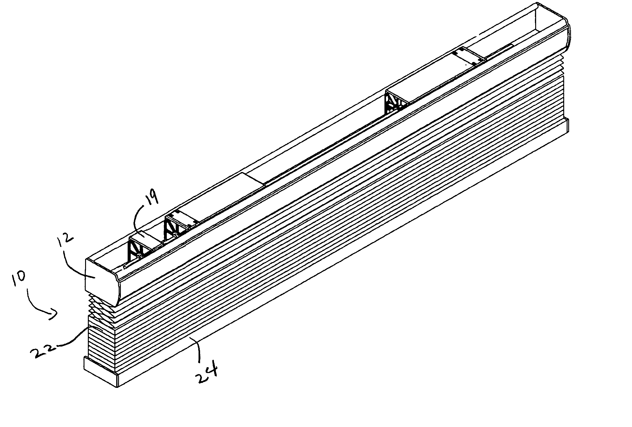
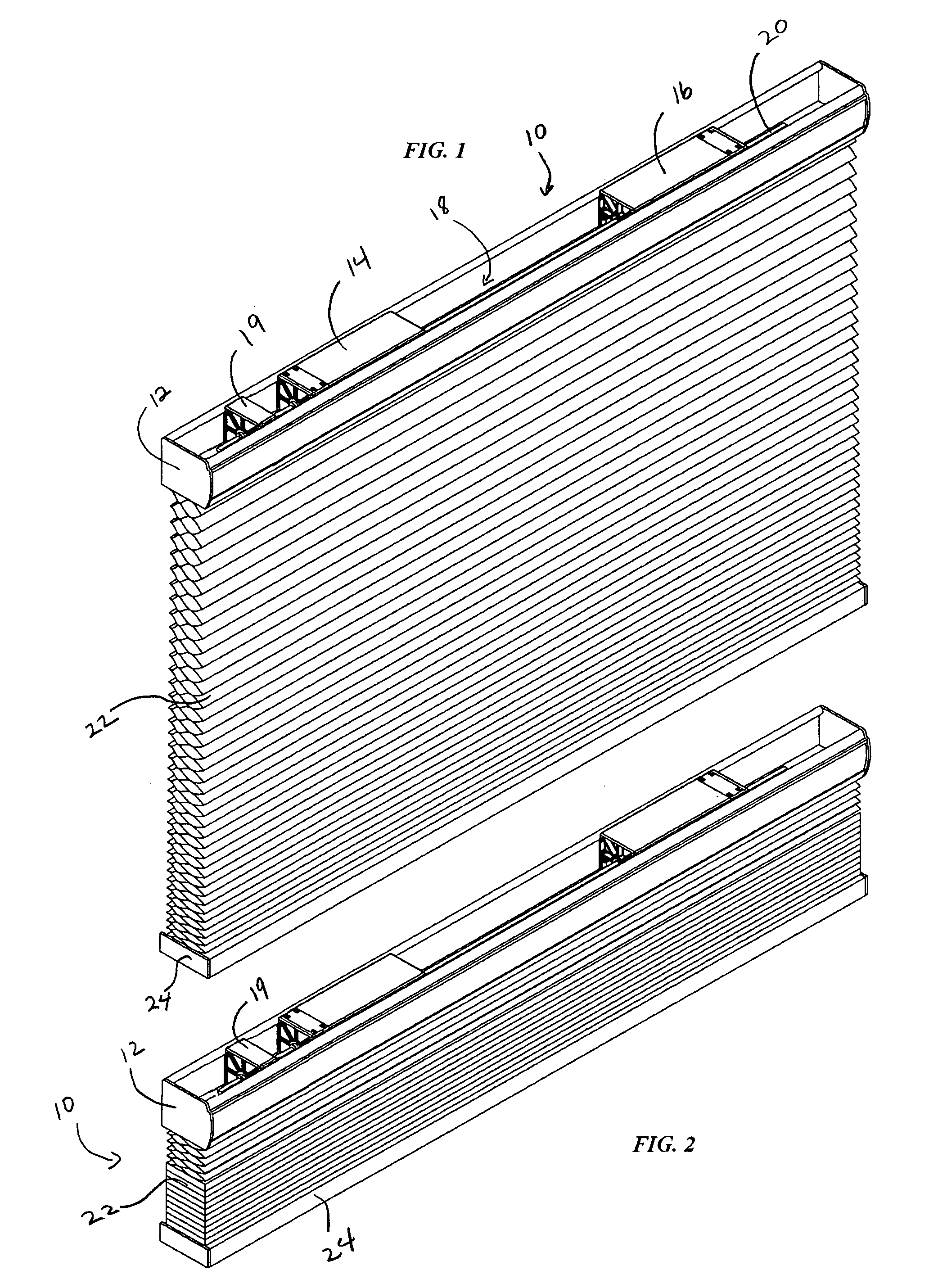
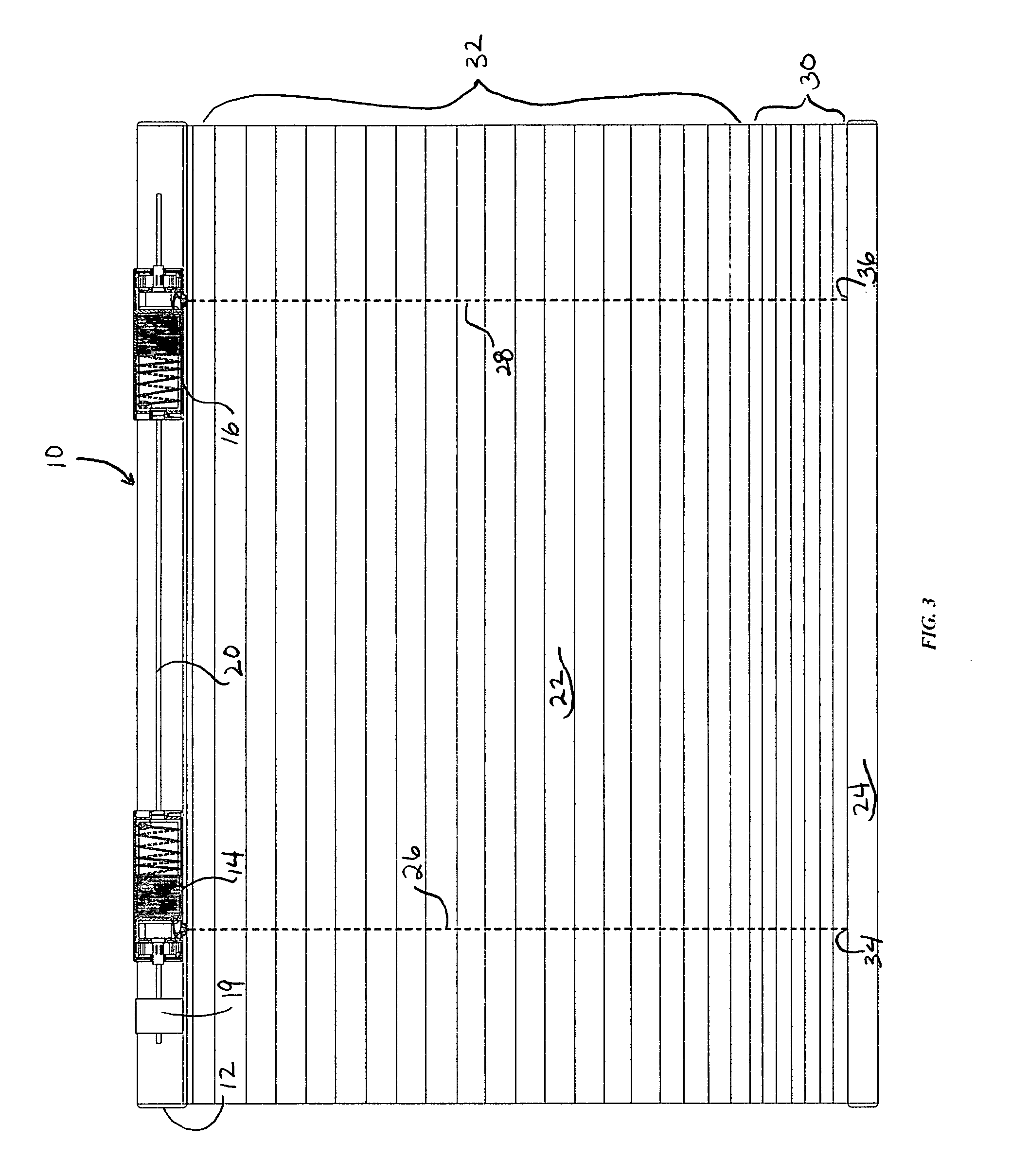
[0029]Referring to FIG. 1, a preferred embodiment of the present invention is shown. Window covering 10 includes a head rail 12, a pair of control modules 14, 16 positioned within a channel 18 of the head rail 12 about axle 20. A window cover member is also provided comprising window cover material 22 and weighted element, such as bottom rail 24. As shown, the window covering 10 is in a lowered position such that the window cover material 22 is extended to cover a window space. In this particular embodiment, the window cover material 22 is shown as a double cell cellular material, however, other materials may also ...


PUM


Abstract

A suspension system for a window covering that eliminates the use of pull cords is provided. The suspension system includes a control module having a winding drum and a spring disposed about an axle. A friction member or reaction member is also provided to offset difference in the force exerted by the spring on a suspension cord versus the weight of the window covering member.

Description

TECHNICAL FIELD OF THE INVENTION [0001]This invention relates to suspension system for a window covering. The suspension system provides a mechanism for control of the window covering without use of a pull cord.BACKGROUND OF THE INVENTION [0002]Window coverings, such as honeycomb window shades, Venetian blinds, and Roman shades typically have a head rail and a window cover material, such as pleated fabric, a plurality of slats, or blind members, which are controlled by cords, whereby a pull cord coupled to the slats, blind members, or fabric can be adjusted to raise or open the window covering. The pull cord extends from a headrail and is manipulated by a user to adjust the position of suspension cords and to thereby adjust the position of the window cover material. One shortcoming of such pull cords is that they require peripheral members that distract from the window cover material and can lessen the aesthetic appearance of the window covering. In addition, pull cords also present...

Claims


Application Information

Patent Timeline
Patent Type & Authority Applications(United States)
IPC IPC(8): E06B9/30E06B9/322
CPCE06B9/322E06B2009/3225E06B2009/3222
Inventor YU, FU-LAIHUANG, CHIN-TIEN
Owner TEH YOR CO LTD
Why Eureka
Try Eureka