Engine including clutch actuator

a clutch actuator and clutch technology, applied in the direction of crankshaft transmission, hydraulic roller based transmission, machine/engine, etc., can solve the problems of increasing both weight and cos

Active Publication Date: 2008-06-05
HONDA MOTOR CO LTD
View PDF19 Cites 24 Cited by
  • Summary
  • Abstract
  • Description
  • Claims
  • Application Information

AI Technical Summary

Benefits of technology

[0006]Accordingly, an outer wall of the engine case can be used as a cover for the clutch actuators. Accordingly, it is not necessary to provide an additional cover, and it is possible to reduce the weight and cost by suppressing an increase in the number of components. In addition, the clutch actuators can be closer to the clutch mechanism. Accordingly, it is possible to simplify and downsize interconnected means provided therebetween.
[0021]Accordingly, a space formed between the clutch mechanism and the cam chain can be effectively used as an arrangement space for the clutch actuators.

Problems solved by technology

One problem with this known structure is that the provision of a special cover for covering the oil passage controlling apparatus (the apparatus that controls the operations of the other components) increases both weight and cost (e.g., due to an increase in the number of components.)
Another problem is that the oil passage controlling apparatus that controls the operations of the other components using the oil passages is located outside the engine case; thus hydraulic pathways provided between the oil passage controlling apparatus and the engine case cross over the engine case.

Method used


Image

  • Engine including clutch actuator
  • Engine including clutch actuator
  • Engine including clutch actuator

Examples


second embodiment

[0111]Next, the present invention will be described with reference to FIGS. 9 and 10.

[0112]Where an engine 13a of the second embodiment mainly differs from the engine 13 of the first embodiment is that the clutch actuators 91a and 91 are arranged below the twin clutch 26, and the same reference numerals are given to parts identical to those in the first embodiment. Thus, the explanation thereof will be omitted.

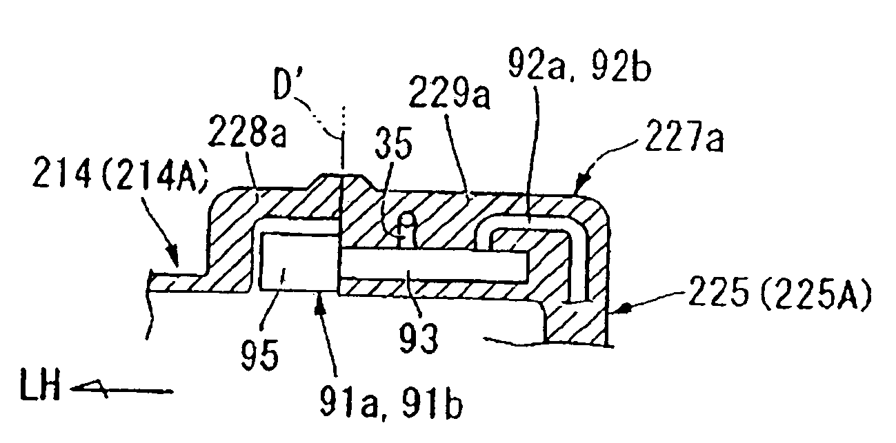
[0113]The respective clutch actuators 91a and 91b are arranged inside an actuator installing part 97a located at a lower portion (below the twin clutch 26) of the clutch case 105A in a state where the axis lines thereof are directed in the left-right direction and they are arranged in parallel with each other and in a vertically aligned manner.

[0114]The actuator installing part 97a protrudes, for example, upward (inside the clutch case 105A) at a lower portion of the clutch case 105A and in the vicinity of the second oil pump 32, and is divided, in the left-right direction, in...

third embodiment

[0120]Next, the present invention will be described with reference to FIGS. 11 and 12.

[0121]Where an engine 13b of the third embodiment mainly differs from the engine 13 of the first embodiment is that the clutch actuators 91a and 91 are arranged behind the twin clutch 26, and the same reference numerals are given to parts identical to those in the first embodiment. Thus, the explanation thereof will be omitted.

[0122]The respective clutch actuators 91a and 91b are arranged inside an actuator installing part 97b located at a rear portion (behind the twin clutch 26) of the clutch case 105A and below the dividing plane B in a state where the axis lines thereof are directed in the left-right direction and they are arranged in parallel with each other and placed above and below.

[0123]The actuator installing part 97b protrudes, for example, forward (inside the clutch case 105A) at a rear portion of the clutch case 105A, and is divided, in the left-right direction, into the crankcase 14-si...

fourth embodiment

[0134]Next, the present invention will be described with reference to FIG. 15.

[0135]Where an engine 13c of the fourth embodiment mainly differs from the engine 13 of the first embodiment is that the clutch actuators 91a and 91 are arranged in front of the twin clutch 26, and the same reference numerals are given to parts identical to those in the first embodiment. Thus, the explanation thereof will be omitted.

[0136]The respective clutch actuators 91a and 91b are arranged inside an actuator installing part 97c located at a front portion of the clutch case 105A in a state where the axis lines thereof are directed in the left-right direction and they are arranged in parallel with each other and placed above and below.

[0137]The clutch actuators 91a and 91b are arranged behind a chain line on the rear side of the cam chain 103 and arranged adjacent to the center of gravity C of the engine located substantially right above the crankshaft 21. The left and right directions of the clutch act...


PUM


Abstract

An engine includes a crankshaft for transmitting rotational drive power to a drive wheel, a clutch mechanism for connecting or disconnecting the transmission of rotational drive power of the crankshaft, and clutch actuators. The crankshaft, clutch mechanism, and clutch actuators are accommodated in an engine case. The clutch actuators control the clutch mechanism and are positioned outside the clutch mechanism, viewed from the crankshaft direction.

Description

FIELD OF THE INVENTION[0001]The present invention relates to an engine including clutch actuators suitable for a saddle-ride type vehicle such as a motorcycle.BACKGROUND OF THE INVENTION[0002]It is known to have an engine having an engine case, wherein on an upper surface of the engine case (e.g., which accommodates a crankshaft, a clutch mechanism, and a transmission mechanism) there is provided an oil passage controlling apparatus that controls switching of oil passages so as to control the operations of other components (e.g., the transmission mechanism). Such an engine structure is known to include a cover which covers the oil passage controlling apparatus (for example, refer to JP-A No. S63-125490.)[0003]One problem with this known structure is that the provision of a special cover for covering the oil passage controlling apparatus (the apparatus that controls the operations of the other components) increases both weight and cost (e.g., due to an increase in the number of compo...

Claims


Application Information

Patent Timeline
Patent Type & Authority Applications(United States)
IPC IPC(8): F16D25/063B62D61/00F01M13/02
CPCB60K17/02F16D25/10F16D25/0638F16D21/06
Inventor OGASAWARA, ATSUSHI
Owner HONDA MOTOR CO LTD
Why Eureka
Try Eureka